This page describes the construction of the attocube rotator. It will eventually include wiring diagrams, operation manual, etc.
Updated Wiring Diagram (12th Jun 2014)
Line 2 on the coldfinger has a short - the spare line 21 has been soldered to pin 2 on the mPuck.
To account for this the fridge's coldfilter board has been swapped over: ie. line 2 is now unfiltered, and line 21 is filtered.
mPuck to Matrixbox lines are:
| mPuck | Matrixbox | Line resistance (ohms) |
| 1 | 1 | 2330 |
| 2 | 21 | 2334 |
| 3 | 3 | 2331 |
| 4 | 4 | 2331 |
| 5 | 5 | 2331 |
| 6 | 6 | 2332 |
| 7 | 7 | 2332 |
| 8 | 8 | 2332 |
| 9 | 9 | 2338 |
| 10 | 10 | 2330 |
| 11 | 11 | 2332 |
| 12 | 12 | 2329 |
| 13 | 13 | 2330 |
| 14 | 14 | 2331 |
| 15 | 15 | 2332 |
| 16 | 16 | 2329 |
| 17 | 17 | 2329 |
| 18 | 18 | 2331 |
| 19 | 19 | 2329 |
| 20 | 20 | 2330 |
--
LaReineYeoh - 12 Jun 2014
Current Rotator Status
Ashwin testing the rotator on the K100 (14th-15th May 2013).
It was reported by Adam B, Oleh and others that the sample wiring keeps shorting to ground when the fridge is cold (but no problems at RT).
So I checked this by cooling the fridge with the rotator, and using a SMU to check for leakage to ground on each pin.
I also checked the operation of the rotator itself, since some people reported that very large driving voltages of 60+V were needed to move the rotator, and that it was getting stuck etc.
At Room Temp with rotator mounted onto fridge:
Rotator:
-Capacitance = 2.07uF
-Moves with Vdrive as low as 25V.
-Moves very fast with Vdrive set at 45V(f = 500hz) --> full 90 deg rotation in about 10 sec
-Angle range (242 --> 100 degrees)
Sample wiring:
-All sample wiring is connected (~2320 Ohms total Resistance from matrix module breakout box to mpuck pins)
-There are no shorts to ground or any shorts to other pins.
At 4K:
Rotator:
-Capacitance = 0.387uF
-Moves with Vdrive greater than 35V.
-Moves fast with Vdrive set at 45V
-Angle range (242 --> 120 degrees)
Sample wiring:
-There are no shorts to ground or any shorts to other pins.
(could not test if wiring was continous since there is no sample)
At Base:
Rotator:
-Capacitance = 0.332uF
-Moves with Vdrive greater than 35V.
-lots of heating! Just with the controller on (and V0 static readout voltage = 0.2V), Tmc went from 55komhs to 35kOhms
-Rotating with Vdrive = 45V and f = 50Hz gives ~90deg of rotation in 10 minutes. and Tmc heats up to about 500mK...but Fridge doesnt crash!
note: theres heaps of drift at base! after the rotator is moved and stopped, the rotator drifts another 2 degrees on its own quite quickly (~30sec).
Sample wiring:
-There are no shorts to ground or any shorts to other pins.
(could not test if wiring was continous since there is no sample)
Summary:
Overall the Rotator seems to be working much the same as it did back when we first installed it in end of 2009...
-looking back at the notes from then, we needed at least 35V to run it at low temp, and now its about 40V so not much different.
-there is slightly more heating because of this...but overall it behaves almost the same with good rotation range and no shorts of the wiring!
-However, as there was no sample, i cannot say for sure whether the sample wiring remains intact and continuous all the way down to rotator.
--
AshwinSrinivasan - 16 May 2013
Rotator Problem and Fixes
AttoCubeRotatorProblemsSolutions
Experiments on Rotator
HANDLING NOTES: When mounting a sample or any of the plates onto the rotator, please be careful not to twist the rotator plate whilst it is off!! This torque eventually damages the track and the stick-slip mechanism on which the rotator works. If you need to put a sample on or take one off please power up the rotator and move it to a position where you can work then switch it off. If the rotator is twisted too much whilst off, the corresponding angles do not necessairly reset properly with the controller let alone the software on the PC - hence you may find that the angle readings may be off by a fair amount. The only thing that can be done in this case is to reset and restart the controller.
LEMO connector: please do NOT move the LEMO connector because the joints are not very strong as only the very thin inner conductor is soldered.
Installation of Rotator and First Experiments (2009)
AttocubeUsingANC350AndDaisySoftware - Basic instructions on using the controller and the daisy software for manually controlling rotator. This page also has a pdf copy of the ANC350 and Daisy software manual (sorry, QED group access only).
AttoCubeChangingV0AngleAndHeatingTest - Fridge heating and power calibration
AttoCubeLabViewControl - Description of Labview programs for using the rotator.
AttoCube2degAngleCallibration - details of the experiment on a 2DEG (updated with lots of data 25/09/09)
AttocubeOlehs100HoleWire - details of experiments on Oleh's hole wire + more drift testing and stuff
AttocubeMoreRotatorTestingForRSI - more testing of the rotator including power vs rotation rate, angle v V0...
Still need to:
- Try out V divider/amplifier with controller box using lockins
- Rotates at T<100mK.
- Wires - All wiring seems to be working...including rotator cryocable/coax, and sample loom soldering at mpuck. One or two pins seem to have higher resistance than others, but then upon checking again later, the resistance are back to normal...dodgy wiring in electrical box?
- Rotation angle limited to ~70 degrees on first cooldown (~200 --> ~270 deg)
- Rotator rotates at room temp even with cryocable! (although slower than usual due to the higher resistance).
- Seems like for each cooldown, the rotator needs higher voltages to work... first time it would run with 20V driving voltage, now needs 30+... -- AshwinSrinivasan - 22 Nov 2009
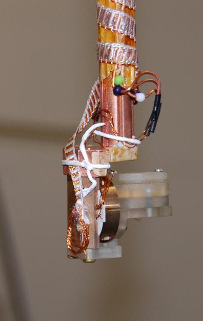
Final setup: Rotator on Cold finger in Perp config
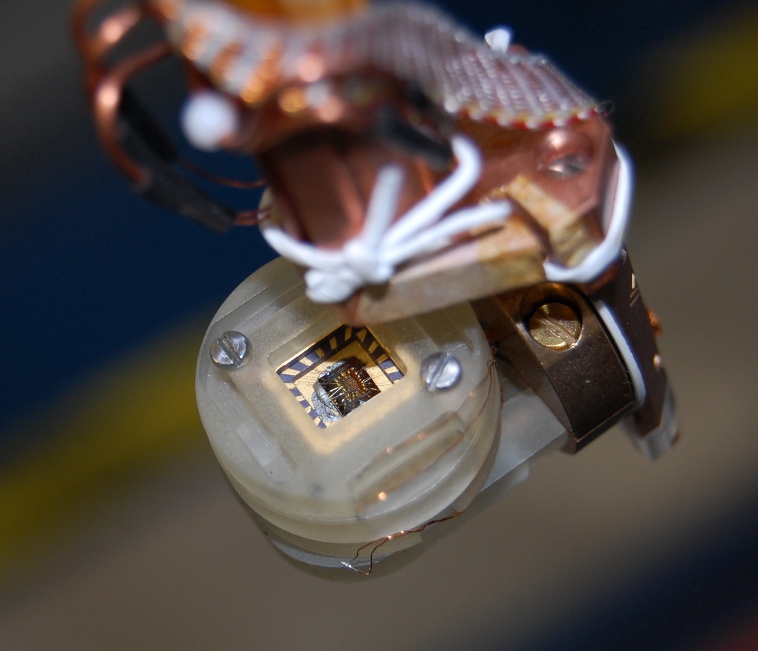
 Laphang's 2DEG sample in sample holder, just before putting into Fridge:
Specifications / Diagnostics
- The resistive readout sensor is 25 kOhms at 100mK according to Ashwin on 3/9/2009.
- update 22/9/09: actually 23.7kOhms V0 --> Gnd (Tmc = 23mK), and this includes ~430 Ohms due to Mn. Therefore R = 23.37 KOhms.
- Update 25/09/09: above using Multimeter --> so its wrong! Redid using 0.5V output from SMU and measured current. R ~ 20KOhms (and varies with B...but effect of that is negligible)
- Resistance of Lasse's copper wire down to 4K ~ 1.1 Ohm.
- Resistance of Lasse's MN wires ~215 Ohm ( Don't know how Lasse got 250+ Ohms on those)
- Cryocable is ~4.2 Ohm (all these resistances are RT one way...)
- Markus Janoota sent over the following calibrations for the AttoCube: ANRv51_C3_903_1.pdf and ANRv51_C3_903_2.pdf.
The parallel position ~138 degrees
The perpendicular position ~ 226 degrees
The stop ~ 239 degrees
NOTE: These angles MAY be offset by 40 degrees. (if it is offset, you need to load actor profile using the dasiy software to get it back to the above settings).
Additional Experiments: After Rebuild (2011)
AttocubeAdamFocusing - (Feb/Mar 2011) Angle testing as well as drift in time and B tests
Still To Do
Mechanical
- Try to get larger rotation angle
Electrical:
- Write down the resistances of various components at 4K.
- need to change the existing LEMO connector setup for rotator wiring... (we need proper MCX connectors for coax cables)
Wiring config/setup
Could somebody
PLEASE write here which way around these plugs are - are we looking into or away from them?
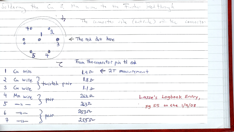
Wiring photograph for female Fischer connector on the top of the fridge (looking down into connector from above the fridge), showing rotator connections:
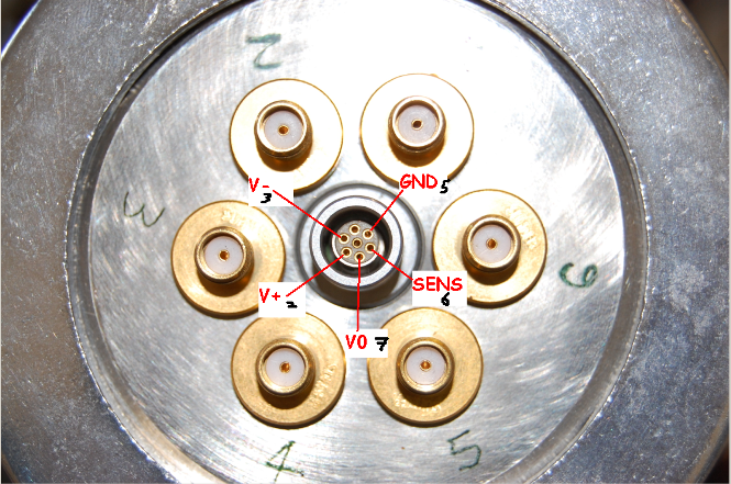
Note: The Red dot on female fridge side Fischer (not seen in photo above) mis-aligns with the red dot on the male connector (From ANC350) by about 5mm.
--
AshwinSrinivasan - 14 Sep 2009
1 Cu Wire, (2 and 3) Cu Wires Twisted Pair - All 1.2 Ohm each down to 4K stage LEMO
(4,5) Mn twisted Pair, (6,7) Mn Twisted Pair - All ~215 Ohm each down to 4K stage LEMO.
1 and 4: Cryocable Shorted
Resistance between pins 1 and 4 should be ~(1.1 + 215 + 8.4) =~ 225 Ohm at Room temp, 201.8 Ohm at base temp.
mpuck wiring config:
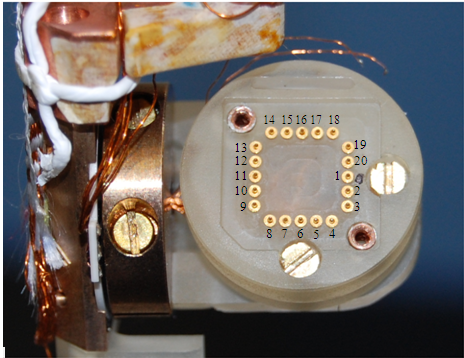
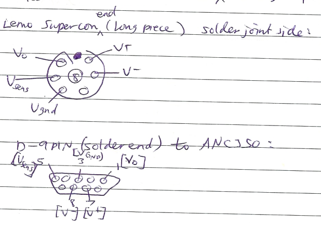
Note: Pins 1 and 5 should be reversed on the 9 pin connector diagram above (V0 = pin 5, sens = pin 1)
--
AshwinSrinivasan - 07 Sep 2009
Designing the System
Notes:
- One of the perpendicular plates has a bad thread (this has been marked with black on the front) - DO NOT use this piece! A second copy will be made shortly.
--
AlexHamilton - 19 Aug 2009
Comments on the Tohoku system, they had two problems. One was getting rid of the heat generated by the rotation and the other was its low torque at low temperature. They only have a few wires, so we may face some trouble. To kill the heat problem they've given up and plan to run it on a 'sample in mixture' system (i.e. top loader).
That shouldn't stop us...
--
AdamMicolich - 19 Aug 2009
Guys - good work on the rotator. With the wiring diagrams, please remember to make it clear which way you are looking at the plug - this is often a source of confusion.
--
AlexHamilton - 27 Aug 2009
Working with the Cryocable is EXTREMELY annoying...
Amyway, we've finished with the LEMO at the mixing chamber, and we're putting a LEMO at the 4K stage as well now. Ted was still trying to solder the cryocable onto the male end of the 4K LEMO at 8.30pm when i left...hopefully he got it. But the female end has been soldered onto Lasse's wires. So once Ted's done it can be connected and clamped down, and the fridge can go in over the weekend...
--
AshwinSrinivasan - 28 Aug 2009
Also we shortened one of the clamps (the top one closest to the 4K stage), because there wasn't enough room for the cryocable to bend at the top with the lemo there as well...
--
AshwinSrinivasan - 28 Aug 2009
 Wiring photograph for female Fischer connector on the top of the fridge (looking down into connector from above the fridge), showing rotator connections:
  Note: Pins 1 and 5 should be reversed on the 9 pin connector diagram above (V0 = pin 5, sens = pin 1)
-- AshwinSrinivasan - 07 Sep 2009
Designing the System
 Copyright © by the contributing authors. All material on this collaboration platform is the property of the contributing authors.
