Cecile3rdDippingAt4K
3rd dipping at 4K (the right one?)Tests at Room Temperature
2T Measurements
Use of the sensitive power supply : 3mV, 10 nA max 4-6 : 2,2 nA 4-12 : 2,2 nA 4-13 : 2,8nA 4-18 : 3,5 nA 4-16 : 3,6 nA Leakage current 4-10 : 2,8 nA R2T (4-6) = 1,36 MOhms4T Measurements
Use of the AC Lock-in Amplifier : Excitation 17Hz 500 MicroVolts Gate ungrounded 13 - 16 : 120 (In) -7 (Out) 12 - 8 : 121 (In) -7 (Out) 12 - 13 : 1 (In) 0 (Out) 8 - 16 : 7 (In) 0 (Out) All results in micro Volts. Intensity through the Hall Bar : 6,5 nA R4T = 18,5 kOhmsRF Resonance
- What is the RF power input?-- AlexHamilton - 20 Apr 2010
Resonance at 4K - 09/04/2010
Resonance_at_4K.txt The resonance had shifted during the night, it is now less important 335MHz (more similar to what Lasse and Ben got) at 0 gate voltage. And it is now possible to match the resistance by changing the gate voltage.(RF Power : -30dBm)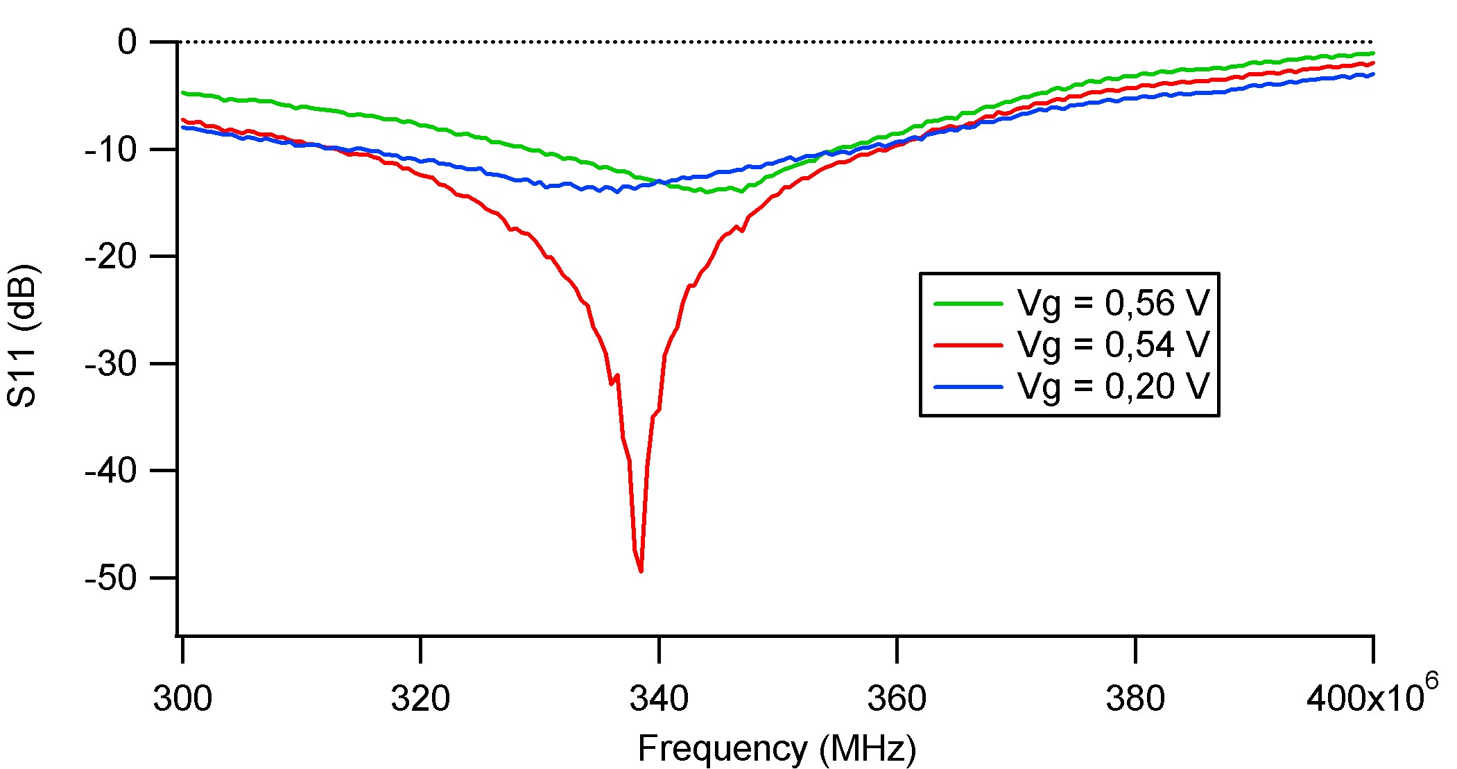
- Cecile - you should put the FILENAME and location of where this data is stored.-- AlexHamilton - 20 Apr 2010
S11 fonction of the gate voltage
 We can clearly observe a resonance which is really sharp and deep, but for a value of gate voltage of 0,54 which is much more than what Ben and Lasse observed. The matching resistance probably changed and is now much more important.
Transfer Function
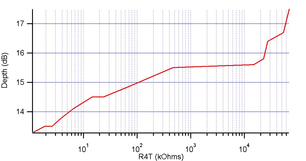 The transfer function is really similar to what Ben got , but I cannot plot for higher resistance because the measurements where not sensible (cf text file attached).
 - Can you plot against R2T? -- AlexHamilton - 20 Apr 2010
- I wasn't able to plot it against R2T or R4T because I wasn't able to read the current which was flowing through the Hall Bar, which was too low.
Resonance at 4K - 14/04/2010
Transfer Function
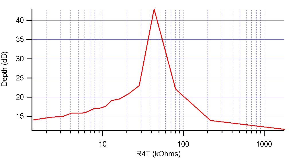 In this graphic we can notice that now the matching occurs at 35 kOhm, which is really close to what Lasse got (55kOhms).
Tests with the Demodulation Circuit :
Parameters
In order to test the demodulation circuit, we need first to make a list of all the parameters that can impact Vr, the voltage output ( Vr=sqrt(Vx^2+Vy^2) ): - Frequency of the power supply : Linear dependance : Vr = -376.5+1.13*f(MHz) - Amplitude of the power supply - Phase shifter - Amplifier - AC Lock-in amplifier settings : excitation amplitude - Resistance of the device (-> that's what we want to calibrate) : 600 MicroVolts of sensitivity for a resistance range of 10 000 Ohms -> Obviously not enough! To see if we can follow the shift in the Resistance of the device with the demodulation circuit, we put a square wave oscillation excitation on the gate. We choosed the offset and the amplitude of the square wave oscillation so that we were on the slope of the transfer function.Configuration 1 :
Frequency of the gate oscillation (square wave) : 5 kHz Offset 0.2V Amplitude 0.1V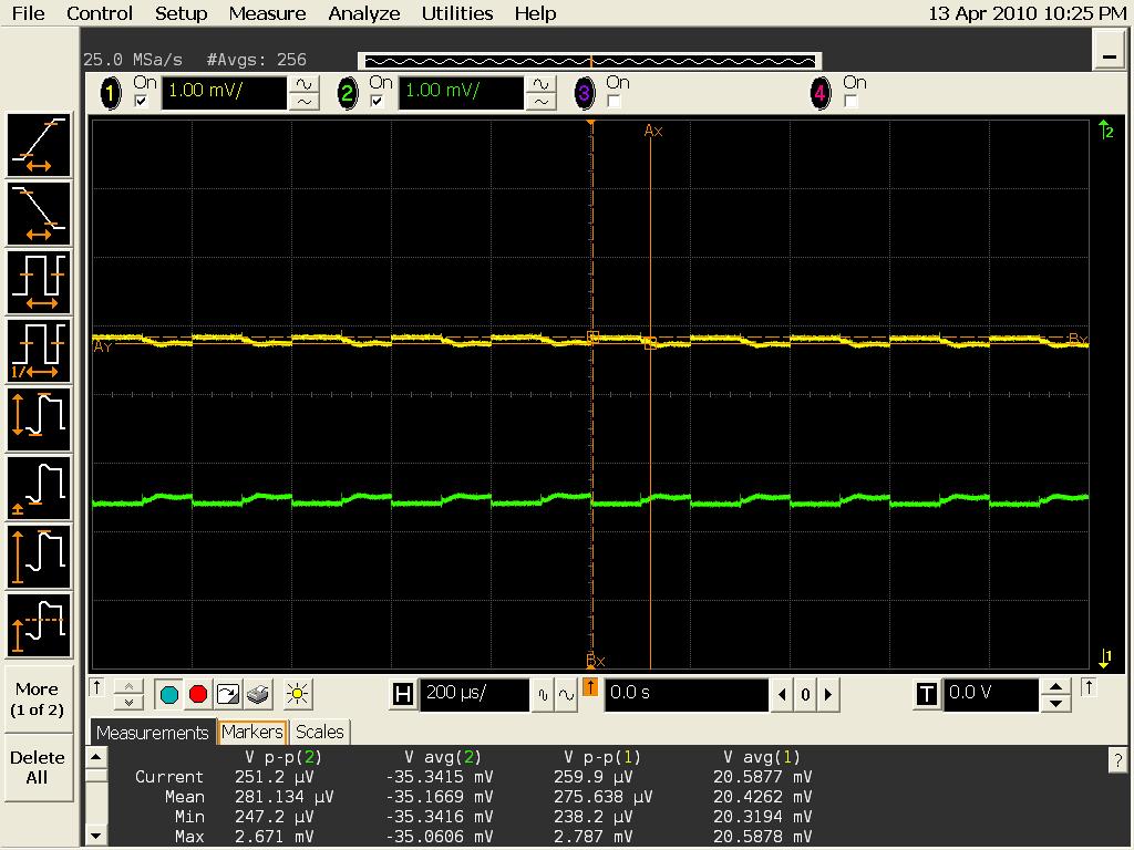 The signal in yellow corresponds to the inphase and the one in green to the outphase.
We can observe a slight asymetry in the signal trace during the falling time. Relaxation Process, RC Time constant, 2nd Order Answer?
With Igor, I represent Vx (Inphase Signal from the Demodulation Circuit):
 Level of Noise : 60-80 MicroVolts
Relaxation time when voltage down 50 MicroSeconds
Configuration 2 :
Frequency : 5 kHz Offset 0.2V Amplitude 0.1V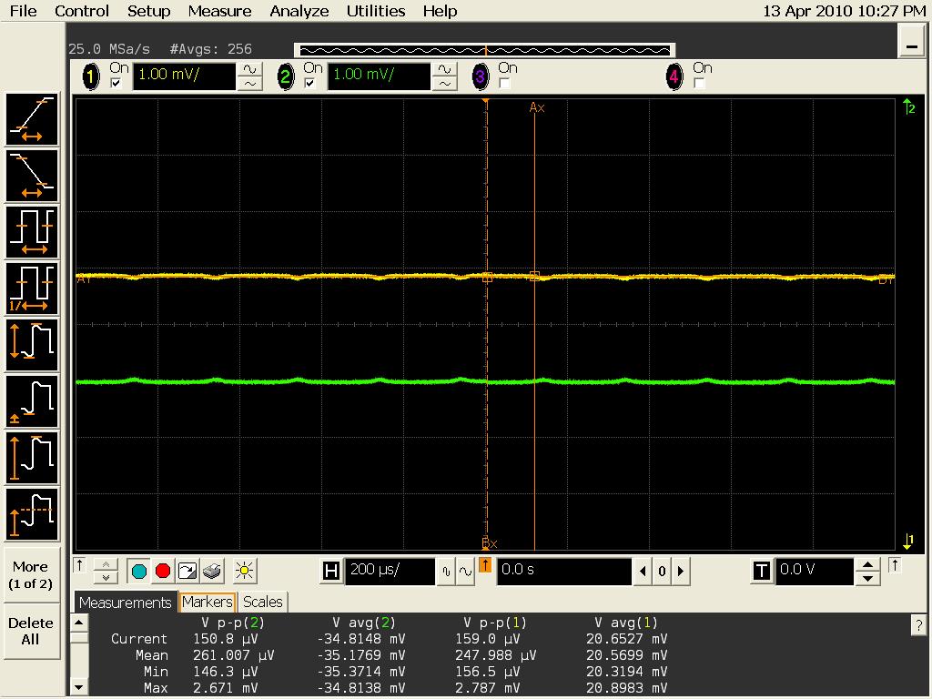
Tags
Comments
How does this resonance compare to last time? It would be good to put a few lines at the top to explain what is different between this and the previous attempt. -- AlexHamilton - 07 Apr 2010| I | Attachment | Action | Size | Date | Who | Comment |
|---|---|---|---|---|---|---|
| |
COnfig2Igor3.jpg | manage | 895 K | 20 Apr 2010 - 07:29 | CecileHeraudeau | |
| |
Config2Igor.jpg | manage | 909 K | 20 Apr 2010 - 07:18 | CecileHeraudeau | |
| |
Config2Igor2.jpg | manage | 852 K | 20 Apr 2010 - 07:23 | CecileHeraudeau | |
| |
RT1.JPG | manage | 121 K | 07 Apr 2010 - 05:35 | CecileHeraudeau | |
| |
Resonance.jpg | manage | 64 K | 09 Apr 2010 - 07:52 | CecileHeraudeau | |
| |
Resonance_at_4K.txt | manage | 2 K | 09 Apr 2010 - 05:54 | CecileHeraudeau | |
| |
S11vsVg.jpg | manage | 183 K | 20 Apr 2010 - 06:01 | CecileHeraudeau | |
| |
S11vsVg2.jpg | manage | 183 K | 20 Apr 2010 - 06:02 | CecileHeraudeau | |
| |
TransferFunction2.jpg | manage | 109 K | 19 Apr 2010 - 07:43 | CecileHeraudeau | |
| |
config2.jpg | manage | 123 K | 19 Apr 2010 - 08:03 | CecileHeraudeau | |
| |
config3.jpg | manage | 119 K | 19 Apr 2010 - 08:03 | CecileHeraudeau | |
| |
transferfunction.jpg | manage | 130 K | 09 Apr 2010 - 06:04 | CecileHeraudeau |
This topic: QED > WebHome > QedProjects > Cecile3rdDippingAt4K
Topic revision: 10 Jun 2010, CecileHeraudeau
Topic revision: 10 Jun 2010, CecileHeraudeau
 Copyright © by the contributing authors. All material on this collaboration platform is the property of the contributing authors.
 Ideas, requests, problems regarding Foswiki? Send feedback

