ICEcubeGasHandlingCabinet
Installation of the new ICE gas handling cabinet, a manual system in replace of the old IGH to go with the K100Fridge in room LG48. *old IGH's valve 12 finally gave way.Documentation
Any formal company Manuals etc here...Schematics (In-House)
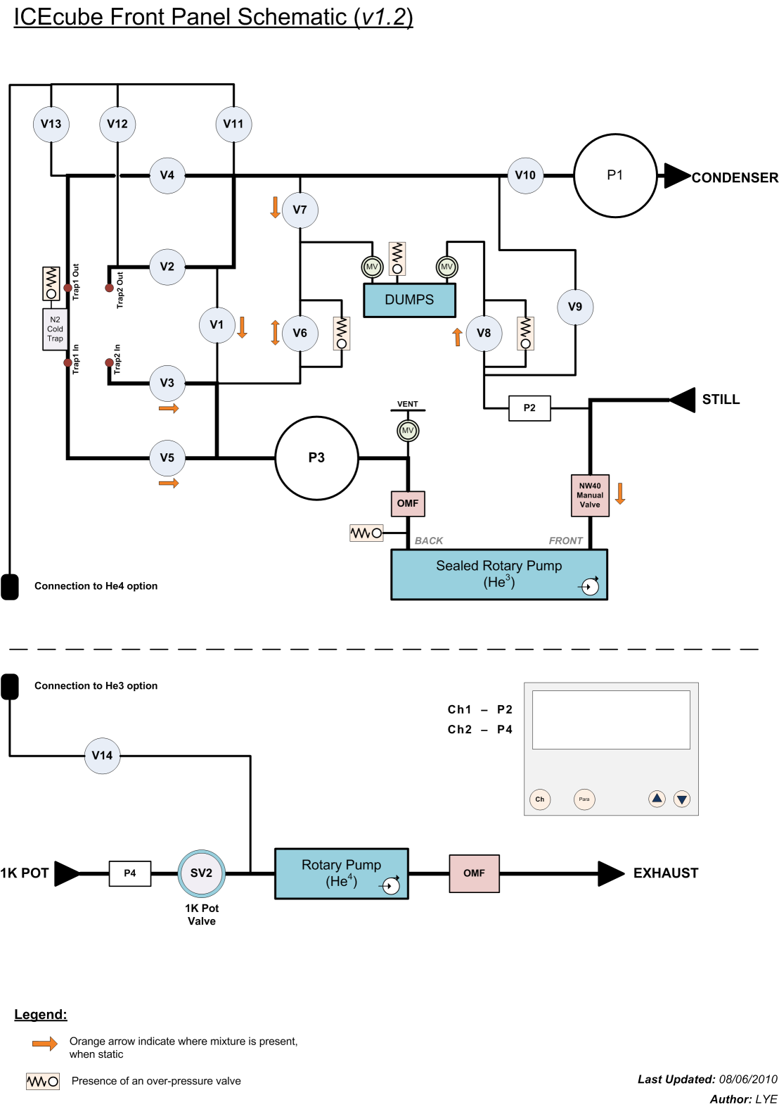
Front Schematic
As seen on the front panel of the ICE cabinet (*needs to be updated) Updated, editable version of the Front Panel Schematic created in MS Visio (of picture below): ICEcube_front_panel_schematic_v1-2.vsd *PDF copies of this avaliable on tne NEWT server:
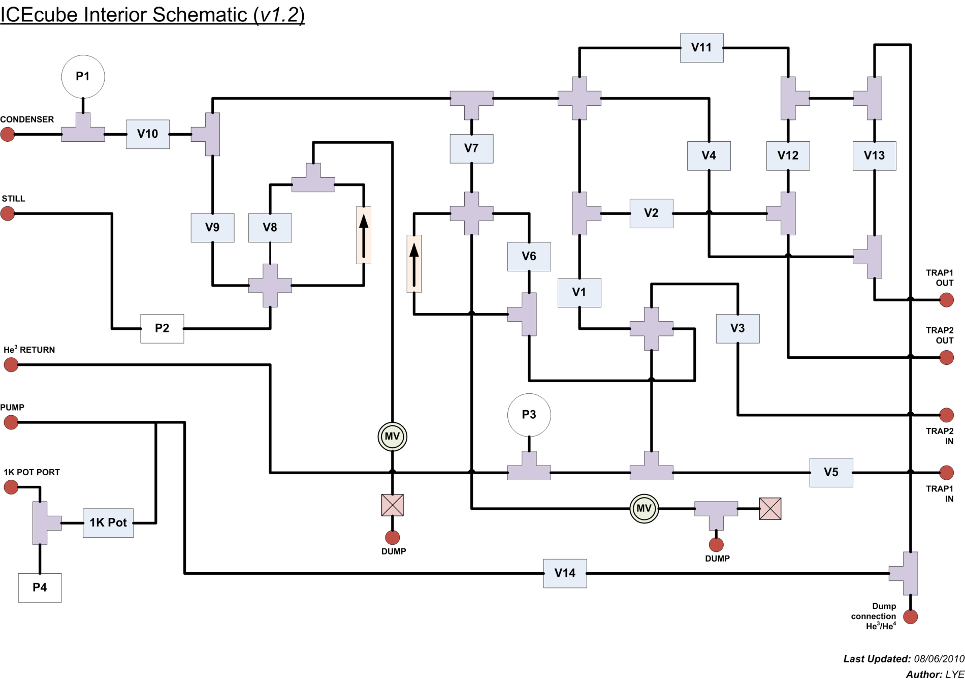
Internal Schematic
Route taken by pipes as seen from the back/inside the ICE cabinet Old file, translated from initial sketch of the tubing (*needs updating): ICEcube_interior_schematic_v1-0.pdf Updated, editable version of the internal schematic created in MS Visio (of picture below): ICEcube_interior_schematic_v1-2.vsd *PDF copies of this avaliable on tne NEWT server: -- LaReineYeoh - 08 Jun 2010
ICEcube to IGH Rough Valve Map
A table of valves which have similar functionality between the ICEcube and the IGH| ICEcube | Old IGH |
| V1 | - |
| V2 | - |
| V3 | - |
| V4 | 12A |
| V5 | 13A |
| V6 | 9 |
| V7 | - |
| V8 | 14 |
| V9 | 3 |
| V10 | 1 |
| V11 | - |
| V12 | - |
| V13 | - |
| V14 | - |
| NW40 | 6 |
| ICEcube | Old IGH |
| P1 | *G1 |
| P2 | P1 |
| P3 | G2 |
| P4 | G3 |
| - | P2 |
Helium Pump Switch Box
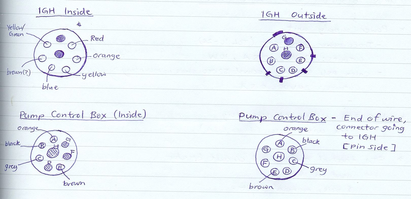
The new ICE box unlike the IGH doesn't have the capability to switch ON/OFF either the He4 or He3 pumps inbuilt, hence a separate switchbox had to be designed to account for this. Circuit diagram for the Helium Pump Switch Box: Pump_SwitchBox_Circuit_Diagram_v2-2.pdf Pinmap for the Ring Lock Connector running between the Pump Switch Box and the existing Pump Control Box mounted on the wall. -- LaReineYeoh - 28 Apr 2010
Tags
Comments


| I | Attachment | Action |
Size | Date | Who | Comment |
|---|---|---|---|---|---|---|
| |
ICEcube_front_panel_schematic_v1-2.png | manage | 167 K | 08 Jun 2010 - 13:07 | LaReineYeoh | ICEcube front panel schematic v1-2, updated |
| |
ICEcube_front_panel_schematic_v1-2.vsd | manage | 241 K | 08 Jun 2010 - 12:53 | LaReineYeoh | ICEcube front panel schematic v1-2, cleaned layout, editable MS visio file |
| |
ICEcube_front_panel_schematic_v1.png | manage | 167 K | 08 Jun 2010 - 12:49 | LaReineYeoh | ICEcube front panel schematic v1.0 |
| |
ICEcube_interior_schematic_v1-0.pdf | manage | 20 K | 08 Jun 2010 - 12:51 | LaReineYeoh | ICEcube internal schematic v1-0, copied from rough hand sketch - needs updating |
| |
ICEcube_interior_schematic_v1-2.png | manage | 140 K | 08 Jun 2010 - 12:52 | LaReineYeoh | ICEcube interior schematic v1-2, cleaned layout |
| |
ICEcube_interior_schematic_v1-2.vsd | manage | 236 K | 08 Jun 2010 - 13:04 | LaReineYeoh | ICEcube interior schematic v1-2, cleaned layout, editable MS visio file |
| |
Pump_SwitchBox_Circuit_Diagram_v2-2.pdf | manage | 21 K | 27 Apr 2010 - 15:18 | LaReineYeoh | Circuit Diagram for the helium pump switchbox to go with the new ICE gas handling cabinet |
| |
pinmap_switchbox_connector_to_controlbox.jpg | manage | 157 K | 27 Apr 2010 - 15:20 | LaReineYeoh | pinmap for switchbox to existing pump control box |
This topic: QED > Main > QedLabStuff > K100Fridge > ICEcubeGasHandlingCabinet
Topic revision: 08 Jun 2010, LaReineYeoh
Topic revision: 08 Jun 2010, LaReineYeoh
Ideas, requests, problems regarding Foswiki? Send feedback