NoiseReductionTechniques
Source : Noise Reduction Techniques in Electronic Systems – Second Edition. Henry W. Ott, 1988.Noise Reduction Techniques At High Frequencies (>10MHz)
Noise sources
- When two circuits share a common ground - ground loop - ground with high impedance - When two circuits share a common power supply - Electric and Magnetic fields - Galvanic actions : use of dissimilar metals - Bending of the cable : triboelectric effect - Conductor motionMethods to eliminate interferences
- shielding - grounding - balancing - filtering - isolation - separation and orientation - circuit impedance level control - cable design - cancellation techniques *Cabling 
- Capacitive coupling : space the cables of 40 times the diameter of the cables.
- Inductive coupling : B factor reduced by physical separation or by twisting the cables
Difference between inductive coupling and capacitive coupling between two cables :
- First : voltage source+ resistance
- Second : one resistance R and voltmeter and variable resistance R2
- If as R2 decreases the measured voltage decreases, electric
- If as R2 decreases the measured voltage increases, magnetic
*Shielding 
- A shield grounded at one or more point shields against electric fields.
- Usually at high frequency ( >10MHz), the shield is grounded at both ends (complication for the magnetic field : a loop is formed).
- At high frequency a coaxial cable works as a triaxial cable (skin effect), removing the noise current flowing from the current path.
- For magnetic shielding : decrease the area of the loop.
- At high frequency, absorption loss is the primary shielding mechanism for both electric and magnetic fields.
Refers p 167 for the skin depths, or characteristic attenuation length, of various metals depending on the frequency.
- At high frequency any solid shield thick enough to be practical provides more than adequate shielding for most application.
- The shielding effectiveness is determined by the leakage at seams and joints.
- For high frequencies, it’s better using a magnetic material than a non-magnetic material.
*Grounding 
- At high frequencies, use of a multiple ground system.
o Low ground impedance
o Short connections between circuit and ground plane (-> PCB)
- Ground Loops
o Remove one of the connections to the ground
o Isolation of the two remote ciruits
§ Transformer
§ Common Mode Chokes
§ Hybrid grounds
§ Optical Coupling
§ Balanced Circuitry
- Guard shield : around amplifier
o Rule : The guard shield should always be connected so that no command mode current can flow through any of the input resistance
As a consequence, we connect the ground of the guard shield to the low impedance terminal of the voltage source
o Every measurement instrument is now equipped with a guard shield -> Connect it to the right place
*Balancing 
- Balance the system allows cancelling in the load the common mode noise voltage spreading through the cables.
- Balance can be preformed by two means
o Symmetry in the circuitry
o Use of transformers to decouple the source from the load
- Balance is additional to shielding
*Filtering 
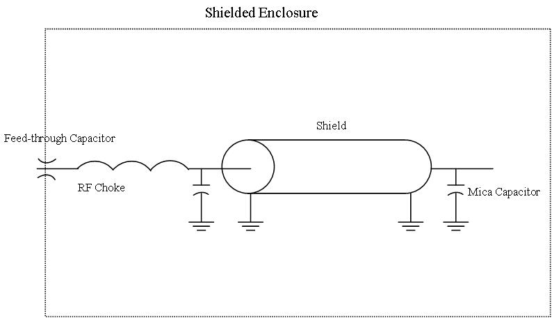
- Use of feed through capacitors when the conductor passes through the shield
- Connect mica or ceramic capacitor with short leads between the conductor and the ground at the circuit end
- Use of a RF choke after the feed through capacitor

Passive components:
- All capacitors are self-resonant at some frequency. - Mica and Ceramic Capacitor are good high frequency capacitors - Air core inductors generates more noise fields than do closed magnetic material core inductors, but the later are more susceptible to interfere with magnetic fields.Tags
Comments
| I |
Attachment | Action | Size | Date | Who | Comment |
|---|---|---|---|---|---|---|
| |
Filtered_RF_circuit.jpg | manage | 24 K | 20 Apr 2010 - 00:44 | CecileHeraudeau |
This topic: QED > WebHome > QedProjects > NoiseReductionTechniques
Topic revision: 20 Apr 2010, CecileHeraudeau
Topic revision: 20 Apr 2010, CecileHeraudeau
 Copyright © by the contributing authors. All material on this collaboration platform is the property of the contributing authors.
 Ideas, requests, problems regarding Foswiki? Send feedback

