|
|
You are here: Foswiki>QED Web>QedProjects>RFDemodulationCircuitTroubleShooting (09 Sep 2014, RoyLi)Edit Attach
RFDemodulationCircuitTroubleShooting
Troubleshooting of the demodulation circuit.PhaseShifter
The purpose of this tests was to determine the impact of the phase shifter in the circuit, and the dependance regarding to the input parameters.Dependance on the Voltage Bias
The reason why we use this Bias Voltage range is because it corresponds to the extreme values used to get a -90Degrees phase shift with frequencies going from 330 to 350 MHz.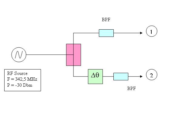
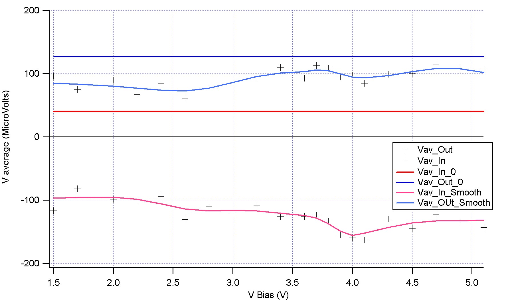
V average
 Source : N>Cecile>Experiment 2204201>Experiment
- Asymetry in transmission through the splitter
- We can average the output of the phase shifting circuit at +/- 50MicroVolts
- The Phaseshifter seems to impact the InPhase Output : problem. Why?
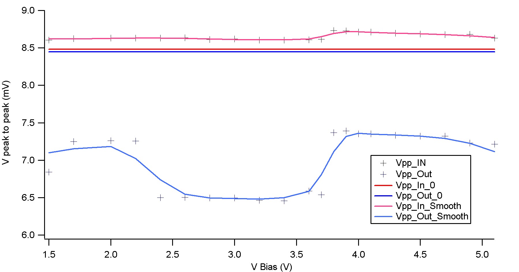
Vpp
 N>Cecile>Experiment 2204201>Experiment
- Attenuation of the phase shifter : -1,5mV
- Dependance on bias voltage
Dependance on the Frequency of the Source
VBias= 3.85V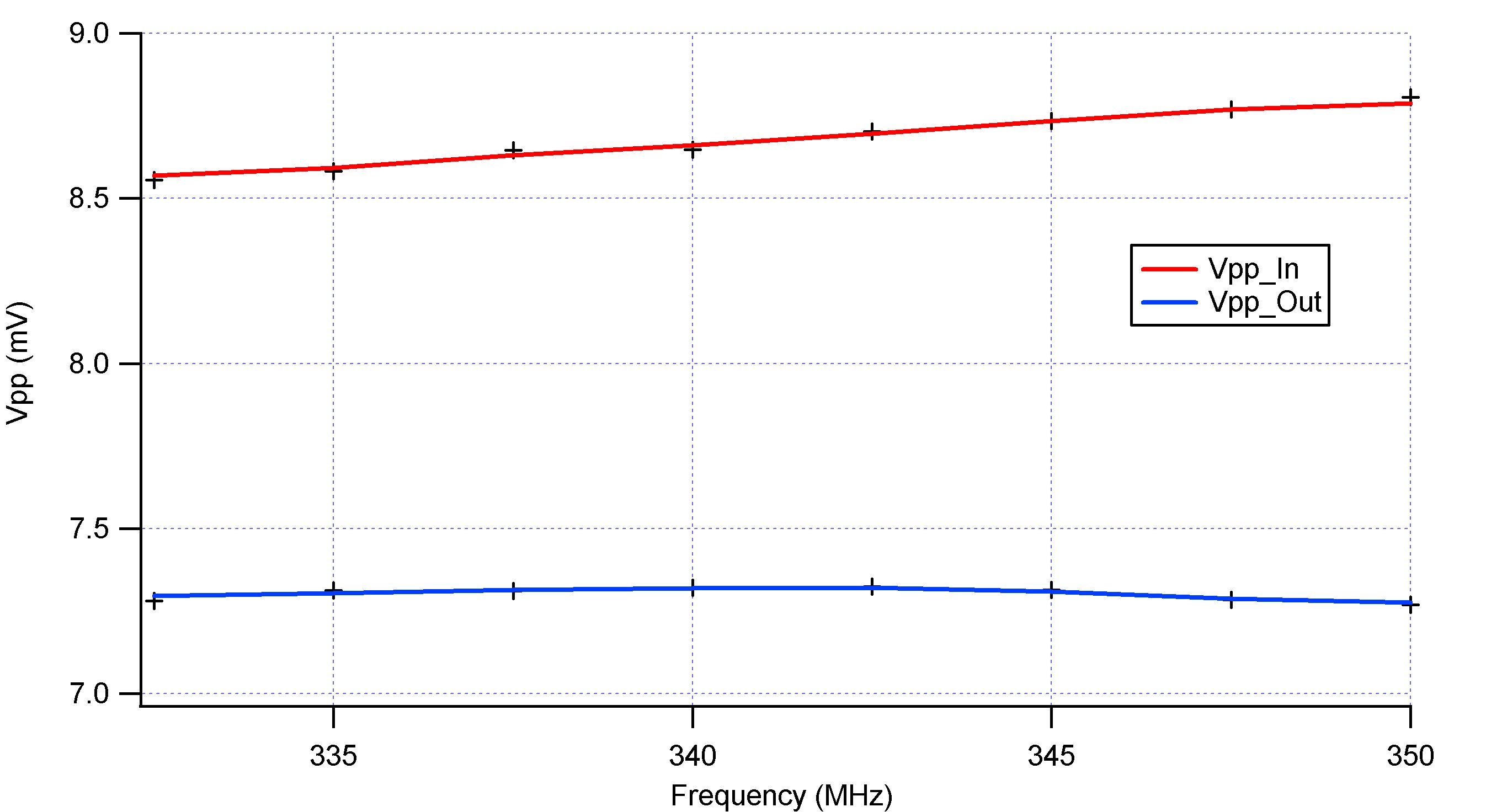 Source : N>Cecile>Experiment 2204201>Experiment_PhaseShifter_Frequency
- Not dependant on the frequency of the RF source considering the frequency range used
Mixer
Limiting power input
Test Circuit
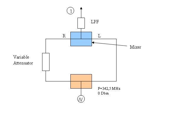
Theory
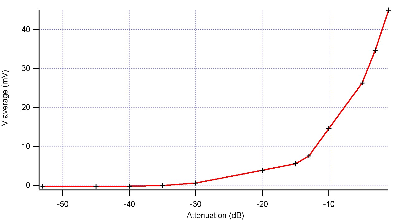
Vamp = Ö(2×Z0×10dBm/10 – 3) Z0=50 W Vamp_Mixer = Vamp1 x Vamp2 LowPassFilter : Vaverage = Vamp_Mixer / 2Experimental trace
 Source : N>Cecile>Experiment 2304201>Experiment
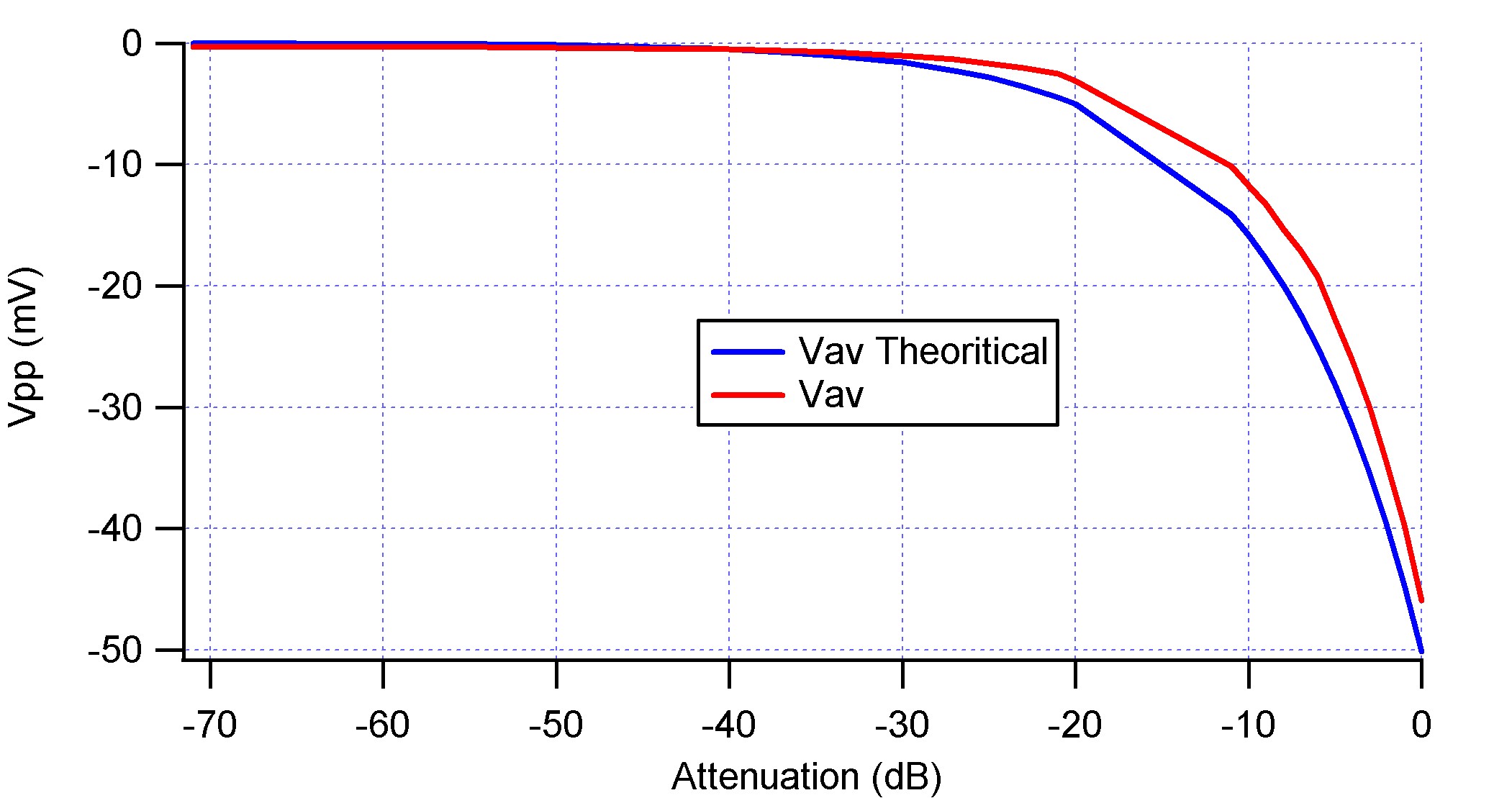
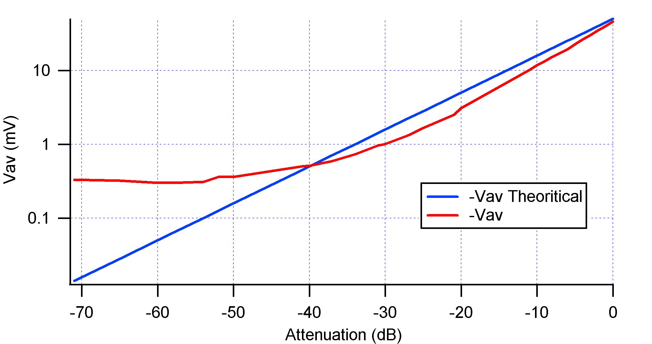
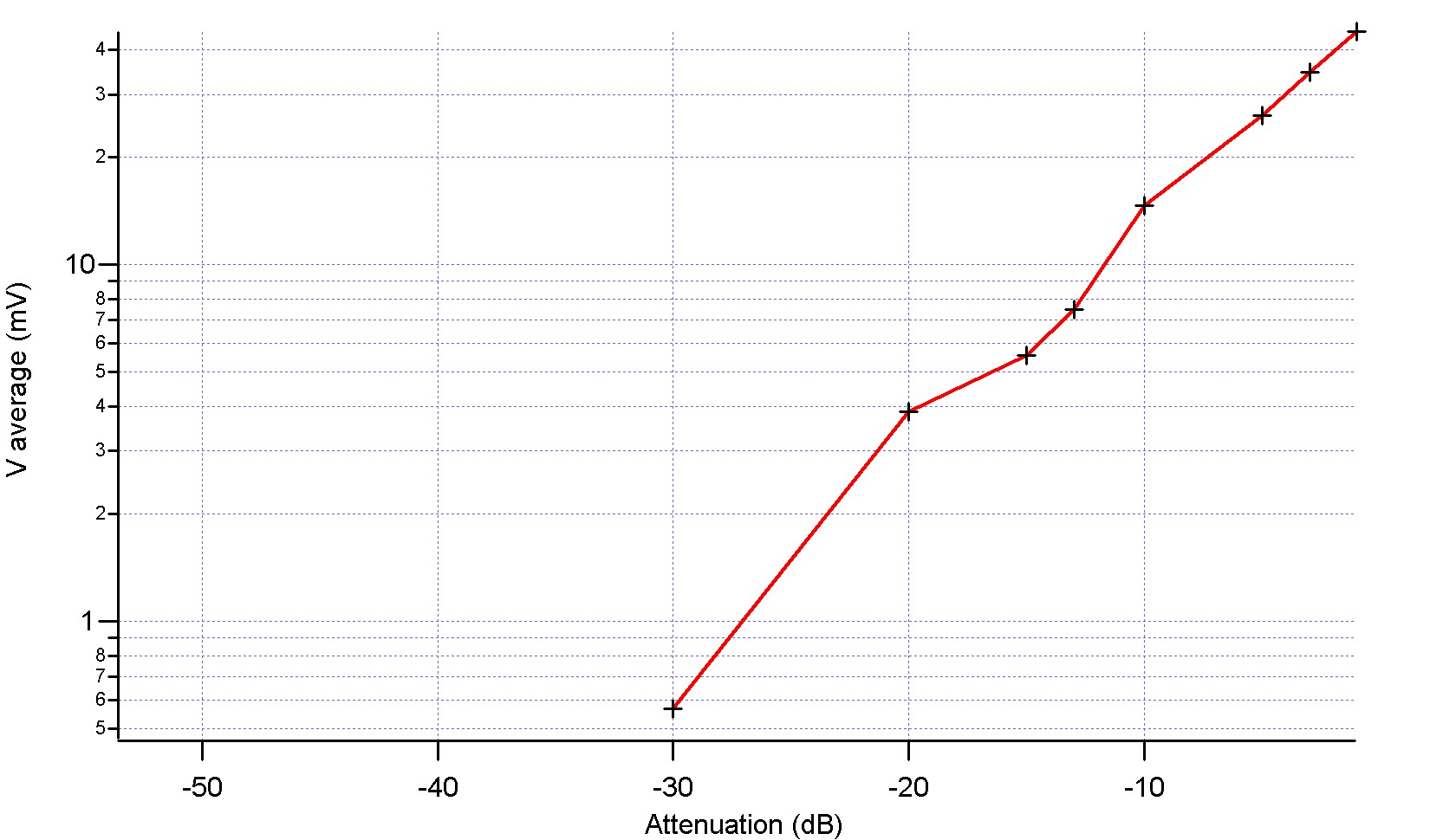
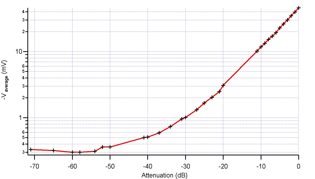
Comparison with theory

Source : N>Cecile>Experiment 2304201>Experiment For the theory data N>Cecile>Experiment 2304201>Calculations (Excel File)
 Source : N>Cecile>Experiment 2304201>Experiment
For the theory data N>Cecile>Experiment 2304201>Calculations (Excel File)
Source : N>Cecile>Experiment 2304201>Experiment
For the theory data N>Cecile>Experiment 2304201>Calculations (Excel File)
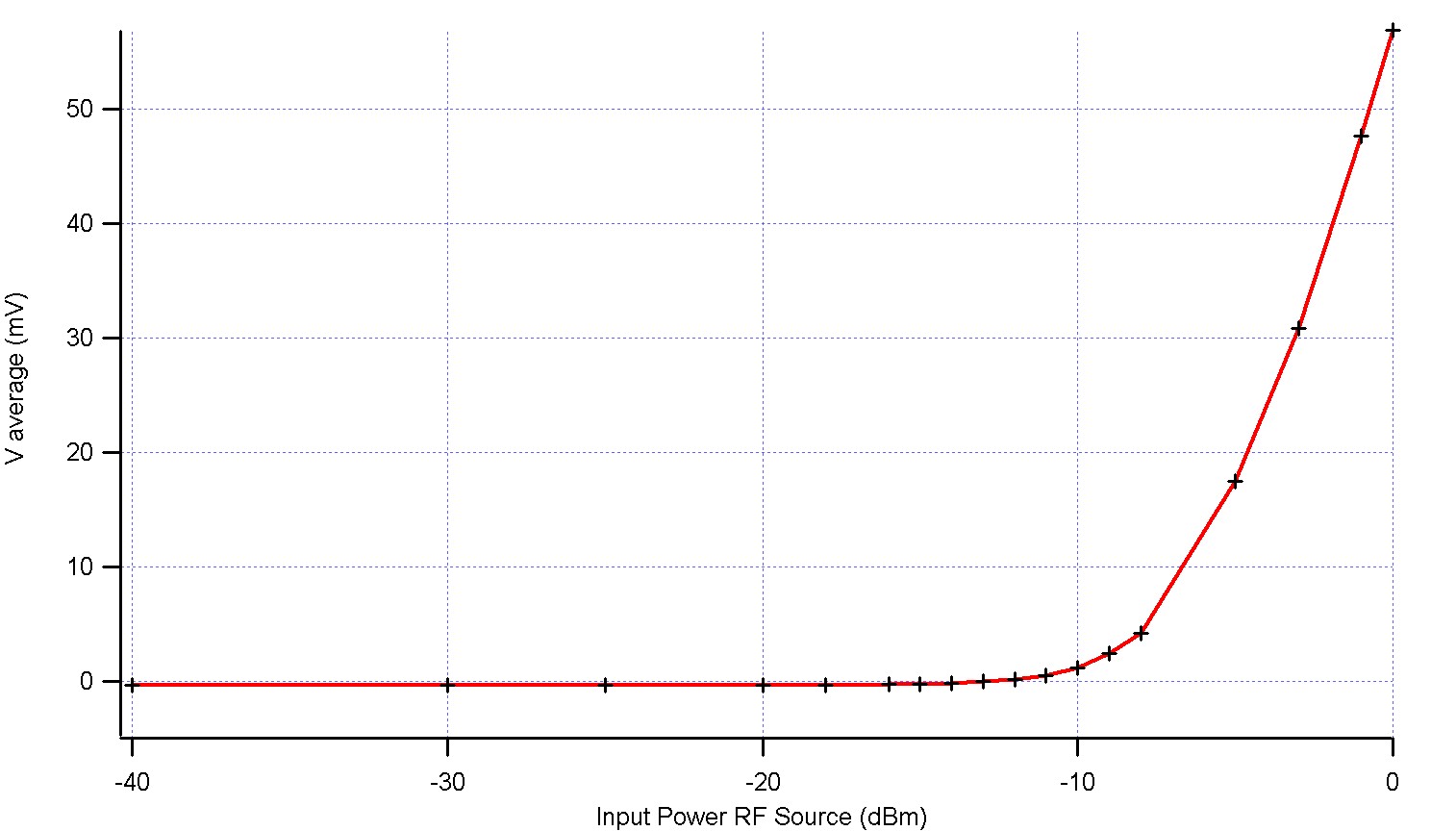
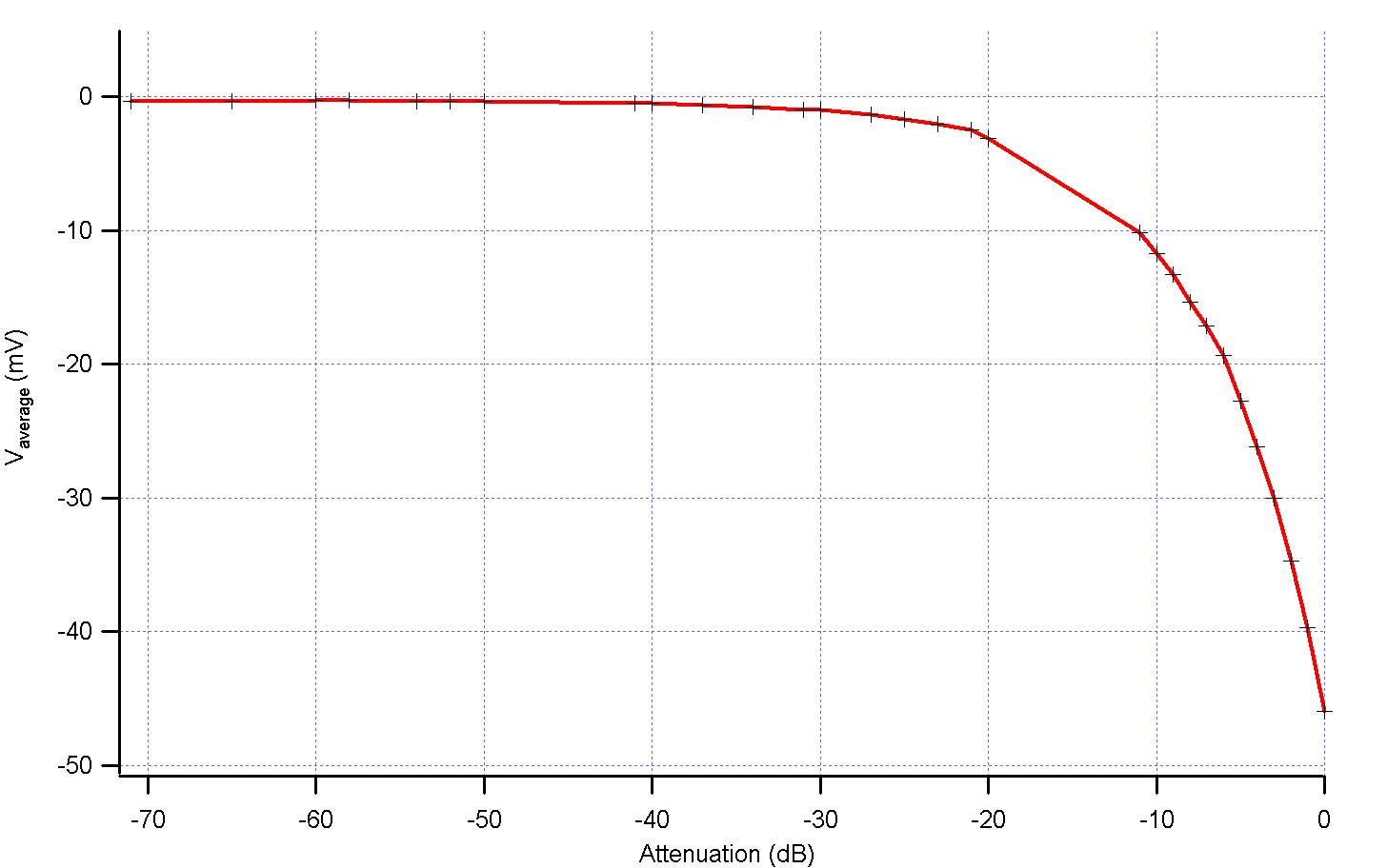
- We can clearly see that above -40 dB of attenuation, the output of the mixer isn't valid.
- What is the limiting parameter now? the input power of the mixer or the noise?
- The mixer has a linear behaviour if we assume that the LO Input power is fixed, so to increase the limit RF input power we just have to increase the LO Input power. Obviously this cannot work all the time, so what's the limit of this technique?
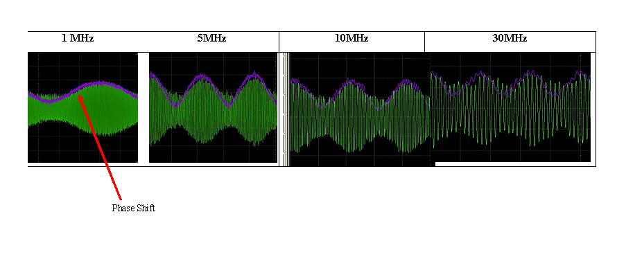
Phase Shift
I also noticed by checking the modulated signal that themixer induced a slight phase shift between the modulation and the modulated signal, depending on the frequency of the modulation.
Source : N>Cecile>Experiment 2704201 It means mainly two things : - First, we will have to wait a certain amount of time before taking the measurements during the calibration of the demodulation circuit with the 4T Measurements. -Second, when we will use the demodulation circuit on the device to detect the quick shifts in the resistance, we will have to remind ourselves that there is a delay between what occurs and what we are measuring.
Demodulation Circuit
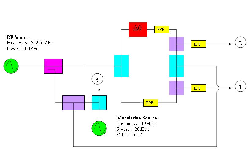
Tests with the completed demodulation circuit, and a mixer as a modulation source Circuit :
 Source : N>Cecile>Experiment 2904201
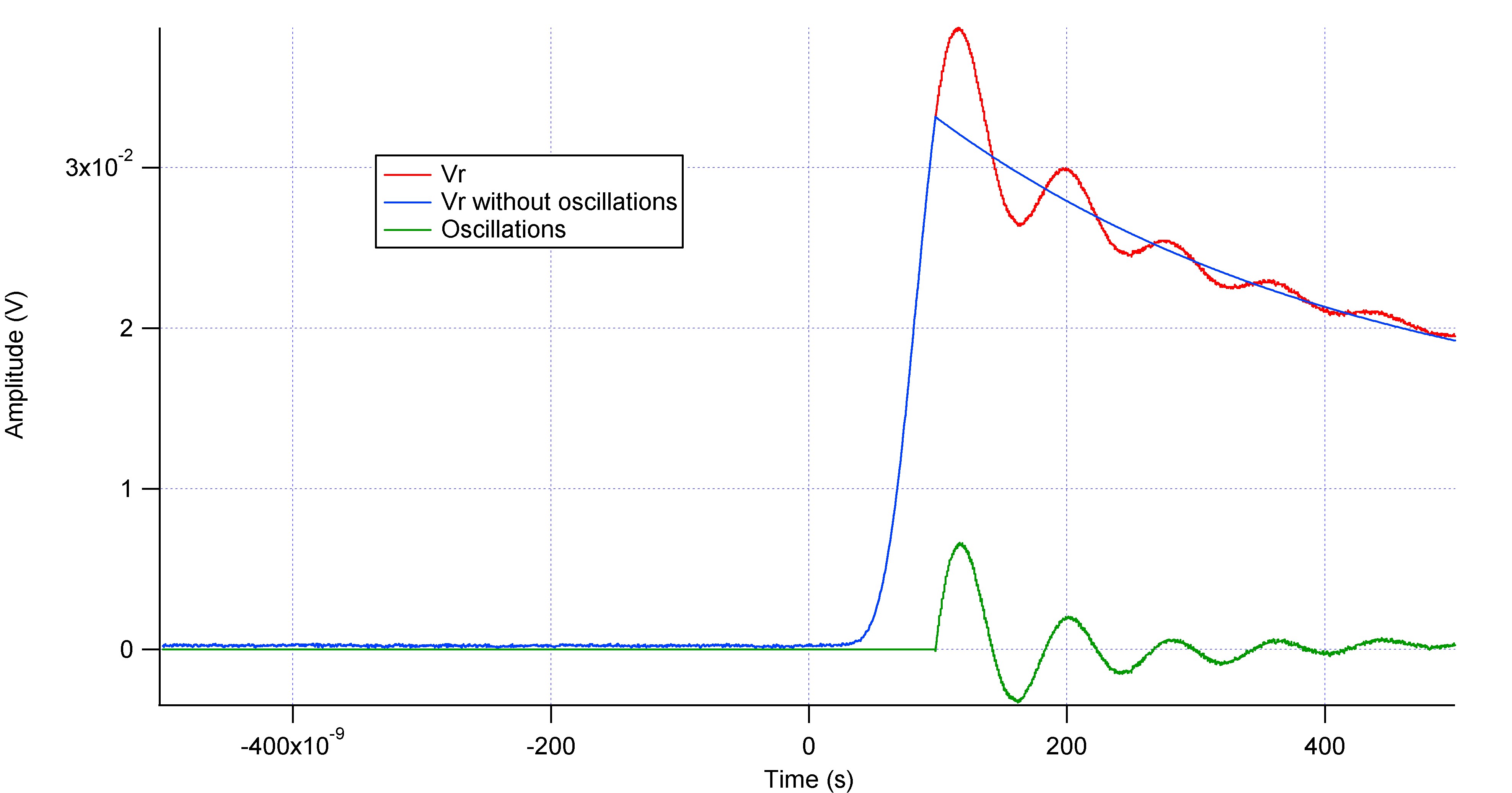
Where f4 = Vr = SQRT ( V_In(t)^2 + V_Out(t)^2 )
Notes :
Source : N>Cecile>Experiment 2904201
Where f4 = Vr = SQRT ( V_In(t)^2 + V_Out(t)^2 )
Notes : - Like what is expected, Vr has twice the frequency of the modulation source
- If we compared the value of Vr_amp = 3.35/2 = 1,67 mV to the one we got from a simulated circuit Vr_amp_th = 1,617mV we can conclude that the demodulation circuit behaves approximately how it is supposed to work.
- Problem : the outphase is much more important than the inphase Vpp_Out/Vpp_In = Tan(Phi) where Phi is the phase shift between the RF source and the modulated signal, then we got Phi = 68.84 Degrees which is an important Shift. Where?
Mixer Experiments 02/05/2010:
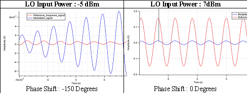
After performing a few tests on the mixer, we finally found out that when the input power in the LO pin is unsufficient, the mixer introduces a phase shift :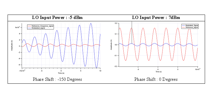 Conclusions :
 - We know have to determine if the phase shift just appears because the LO power was to low, and what is the limiting input RF Power.
- The demodulation circuit was indeed working.
Mixer Experiments 10/05/2010 and 12/05/2010:
Limiting RF Input Power
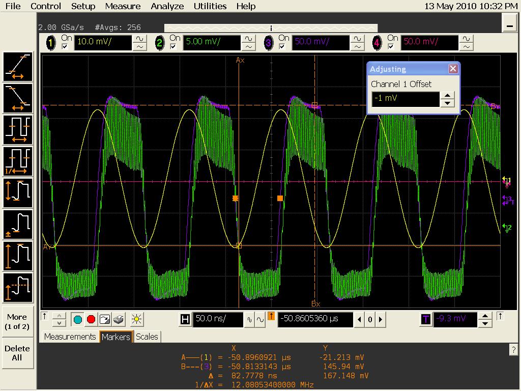
The limiting RF input power for the mixer equals approximately -30dBm for a LO Input Power of7 dBm approximately. Note : the frequency of the modulation source was 10MHz to be in the available range of the mixer, whereas the RF carrier source was at 342,5MHz 10dBm. We also observe a slight phase shift, even at 0dBm RF INput POwer. We found here a phase shift of 13 Degrees approximately.
Answer to a square wave
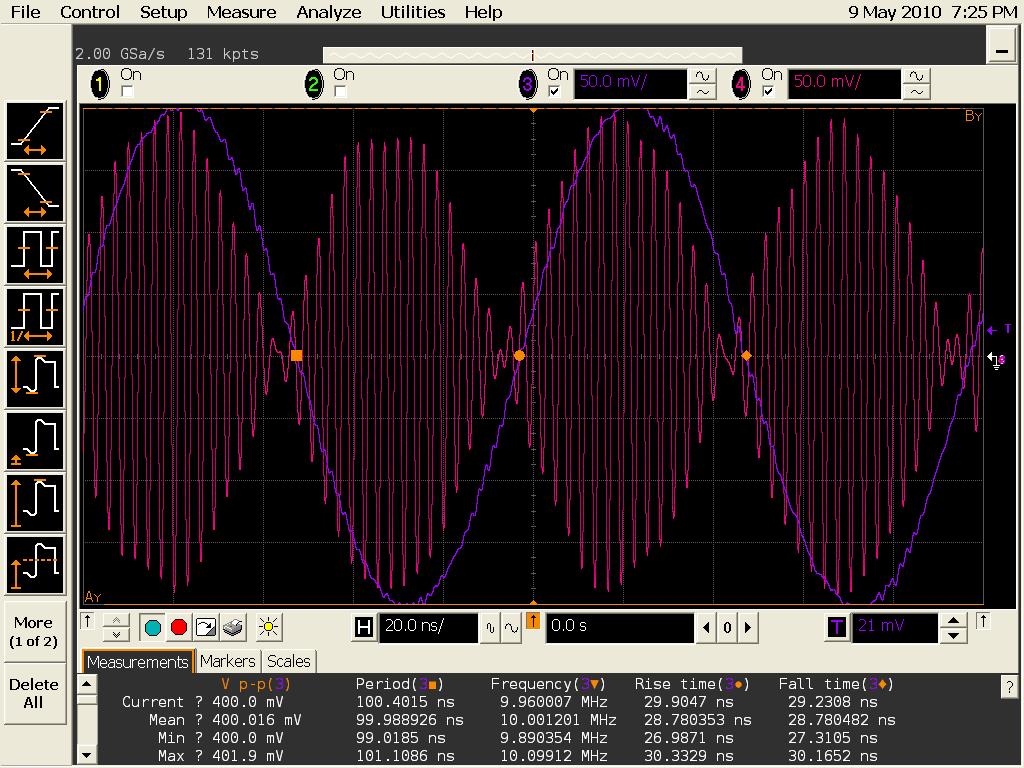
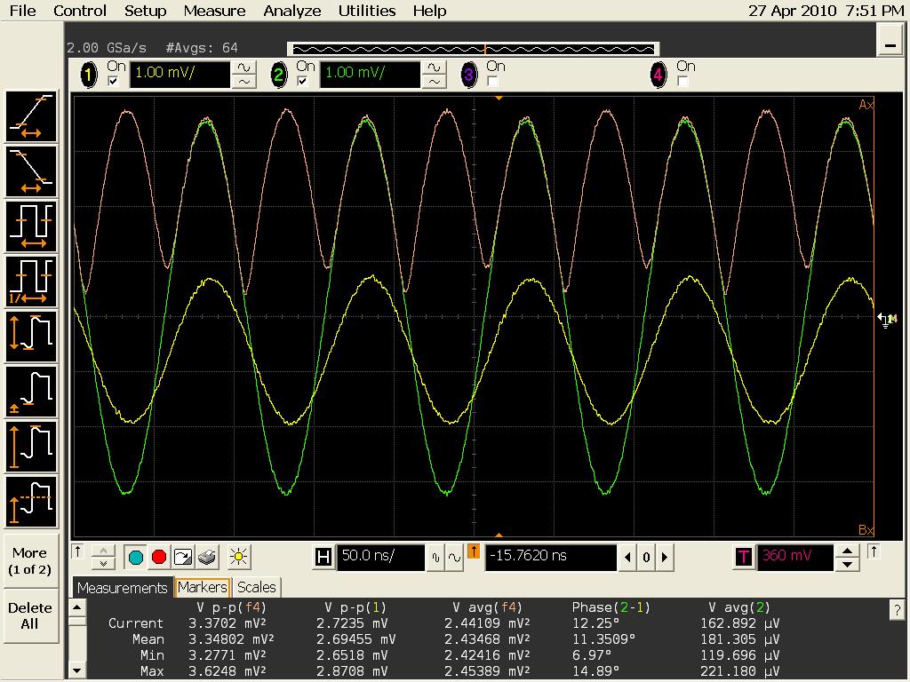
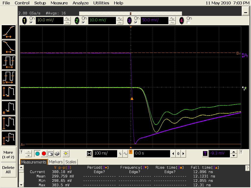
We take the same circuit as previously, with RF Local OScillator at 342,5MHz, 14dBm of power and the modulation source at 0 dBm amplitude (0,447V Vpp), squarewave, 10 kHz of frequency. In yellow, the Inphase.
In green the outphase.
IN purple, the modulation.
We can observe the fact that the demodulated signal is late compared to the modulation, but also a second order oscillation of our circuit response.
Analysis
In yellow, the Inphase.
In green the outphase.
IN purple, the modulation.
We can observe the fact that the demodulated signal is late compared to the modulation, but also a second order oscillation of our circuit response.
Analysis
Delay
Delay of 2.85 E-8 s between the rise of the modulation and the rise of the demodulated signal -> phase shift of the Mixer + distance in the coaxial cables. Good- please give details of calculations!-- AlexHamilton - 13 May 2010 On that matter, I made some research, ths speed of TEM waves in a coaxial cable and particularly microwaves is given by(group velocity) Vg = c * VFwhere c is the speed of light, and VF is the velocity factor wich is given by VF = 1/SQRT(EpsilomR _Dielectric). In our case, the dielectric is the PTFE which gives us VF= 0,695 and Vg = 2,102 E+8 m/s. Finally if the delay is only due to the cables we would have Vg * 2.85 E-8 = 6 m of cables ! The delay must be due to the phase shift induced by the mixers.
Oscillations
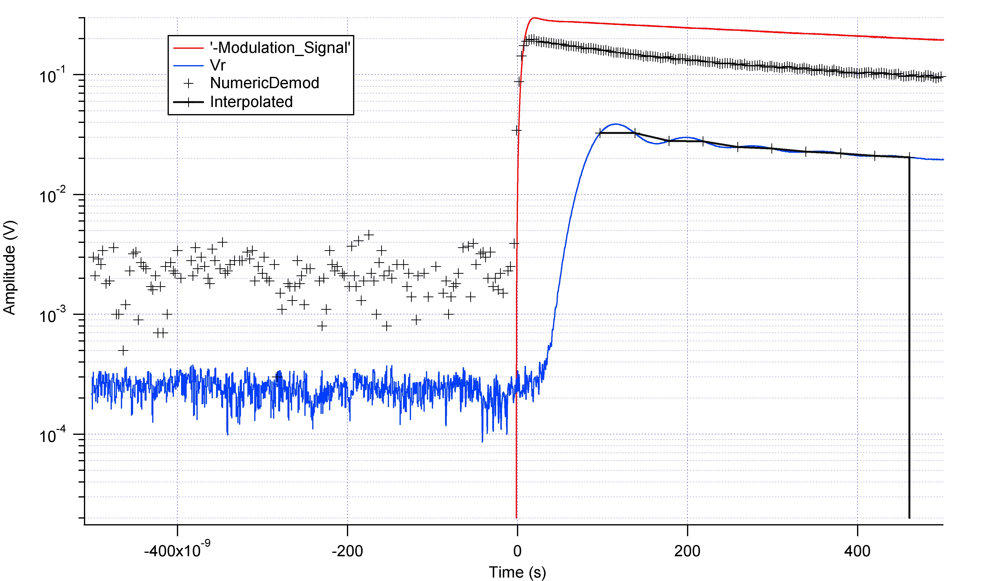
The frequency of the oscillations is 12.38 MHz.Can that really be true - your square wave is at 10MHz -- how can the ringing be only at 12 MHz? -- AlexHamilton - 13 May 2010 My mistake, the oscillations of the modulation source where of 10kHz. What is 'interpolated'? -- AlexHamilton - 13 May 2010 Interpolated means that I picked up some points on the trace to smooth it, but I did a much better work with this one :
 We can assume that it isn't coming from the Phase Shifter since the Inphase also presents the oscillations.
I calculate the attenuation factor of the oscillations using the formula :
Tau = (tn2 - tn1 ) / Ln ( An1 / An2 ) where n1 and n2 are the peak numbers assuming n1 < n2
Averaging, we found that Tau = 7 E-8 s.
Attenuation < 1 % of the final value corresponds to5 Tau, hence
We can assume that it isn't coming from the Phase Shifter since the Inphase also presents the oscillations.
I calculate the attenuation factor of the oscillations using the formula :
Tau = (tn2 - tn1 ) / Ln ( An1 / An2 ) where n1 and n2 are the peak numbers assuming n1 < n2
Averaging, we found that Tau = 7 E-8 s.
Attenuation < 1 % of the final value corresponds to5 Tau, hence
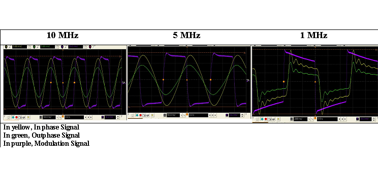
Accuracy indicator : 5Tau = 3,5 E-7 sWhy is modulation signal not a perfect square wave? -- AlexHamilton - 13 May 2010 The reason why the square waves are not perfect is because the operational frequency of the directional coupler or splitter or mixer (>10 MHz) doesn't sensitively match with the operational frequency for the modulation source to induce square waves (the limiting frequency of the source is 40MHz, but the square waves are generated only for f<10MHz). Indeed, a 10kHz square wave signal cannot be sorted out by the splitter and mixer. Anyway, I performed some tests (10MHz, 5 MHz, 1 MHz, 500kHz, 250 kHz, 100 kHz, below results much more seems like previously). I have two conclusions :
- The demodulation circuit only work on square waves of a frequency under 1 MHz. Indeed, there is not only a delay between trhe modulation and the demodulated signal, but the demodulation circuit also smooth the slope of the square.
-

The changes in S11 have to linger more that 5 E-7s to be detected by the demodulation circuit
- The frequency of the oscillations is constant and equals 12 MHz. It is not dependant on the frequency of the modulation source, nore the carrier frequency (for a range going from 330MHz to 350MHz).
 In yellow, we can see the demodulated output signal with the Low Pass Filter
In green, we can see the demodulated output signal without the Low Pass Filter
In purple, we can see the modulation signal
In green, no more oscillations, or excessive smoothing, or even delay. Indeed the 12MHz frequency oscillations were close to the cutoff frequency of the Low Pass Filter (10.7 MHz).The LPF was acting as a dispersive medium.
In yellow, we can see the demodulated output signal with the Low Pass Filter
In green, we can see the demodulated output signal without the Low Pass Filter
In purple, we can see the modulation signal
In green, no more oscillations, or excessive smoothing, or even delay. Indeed the 12MHz frequency oscillations were close to the cutoff frequency of the Low Pass Filter (10.7 MHz).The LPF was acting as a dispersive medium.
Low Pass Filter
this is what I extracted from the datasheet of the Low Pass Filter.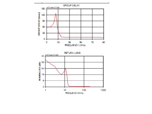 According to MiniCircuits :
group delay is the amount of time it takes for a signal having a finite time duration, such as a pulse, to pass through the filter. Ideally, all frequencies present in the signal should have the same time delay, so that the signal will not be distorted. In most types of filters this is not the case, and group delay defined as dØ/df varies with frequency. For linear phase filters the group delay is constant.
vswr is a measure of the impedance looking into one port of the filter while the other filter port is
According to MiniCircuits :
group delay is the amount of time it takes for a signal having a finite time duration, such as a pulse, to pass through the filter. Ideally, all frequencies present in the signal should have the same time delay, so that the signal will not be distorted. In most types of filters this is not the case, and group delay defined as dØ/df varies with frequency. For linear phase filters the group delay is constant.
vswr is a measure of the impedance looking into one port of the filter while the other filter port isterminated in its characteristic impedance, namely, 50 ohms. Many times, the impedance
match is expressed in terms of return loss. The conversion between return loss and VSWR is
easily attainable using the chart given in Section 0. Most of the filter models shown in this
handbook are designed to present a good impedance match in the passband and a highly
reflective impedance match in the stopband. Typically the VSWR in the center of the
passband is better than 1.2 to 1 and the VSWR in the stopband is typically 18 to 1, very
highly reflective. In these models, both filter ports present a good impedance
match in the passband and stopband. The return loss caracterized the level of sum signal reflected back by the filter. The higher the return loss is the better for the mixer it is because the wave reflected by the Low Pass Filter into the Mixer is recombined with the LO and RF input and generate another IF signal at the same frequency but with a phase shift that modify the apparent demodulated input. See Constant-Impedance IF Bandpass Filters Improve Circuits Performance MiniCircuitsfilters8-2.PDF for more informations.
In order to limit the reflection by the Low Pass FIlters into the Mixer, it is better to use a Constant Impedance Filter with the appropriate IF range.
- From the Phase Delay trace we can interpret the 10 MHz trace we got previously. We are right in the middle of the Resonance in the Phase Delay, meaning that the 10MHz wave is considerably slowing down and gives us this big delay/smoothing.
- From the Return loss trace, we can see that the resonant frequency of the Low Pass is indeed around 12 MHz. Because for a certain frequency the higher the return loss is, the higher the transmission through the Low Pass is, which is the definition of a resonance frequency.
- Try to find a high performance constant impedance low pass filter, even a 250MHz low pass filter can do the trick as soon as the up side band frequency is twice the frequency of the carrier (660MHz), and we don't have any resonance frequency.
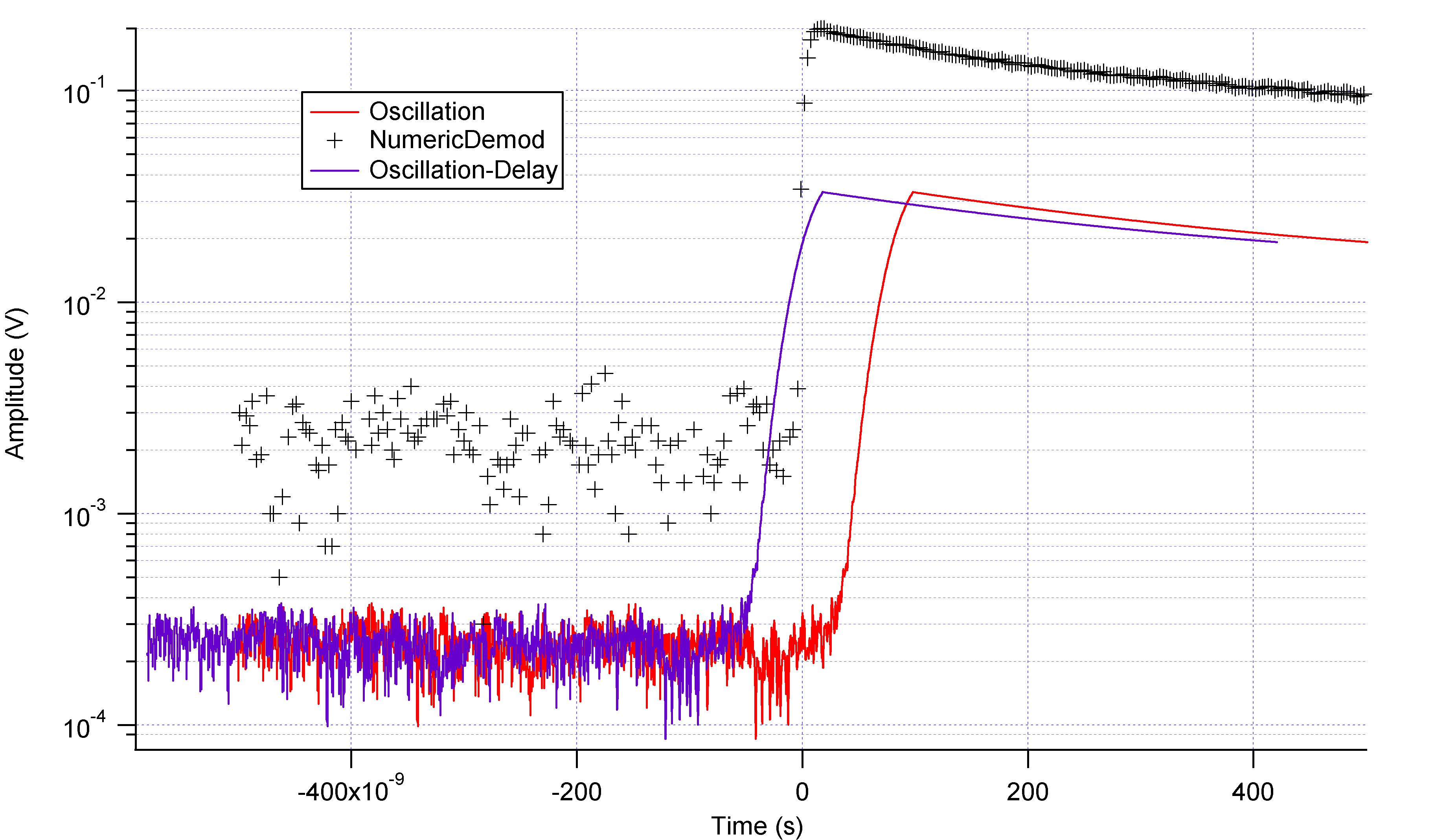
- Perform a numeric demodulation, via IGOR for instance
Calibration
The other interesting thing is that the distance between the two demodulated curves is almost constant, which allows us to calibrate correctly our circuit. If on the logarithmic scale the distance between the two curves is a constant, it means that the ratio A0 between the two amplitudes is a constant.
What we got A0 = (0.16 ; 0.13 ; 0.12 ; 0.10 ; 0.09 ; 0.08) as t increases, but maybe due to the wrong fitting curve on Vr.
The ratio is constant in theory, because the change between the amplitude of the input power and the output is given by the insertion loss of the circuit, which is basically a power ratio (As long as the circuit is impedance matched at 50Ohms, the ratio works for the voltage amplitude as well).
Notes from Brazil: -- AlexHamilton - 03 May 2010
If on the logarithmic scale the distance between the two curves is a constant, it means that the ratio A0 between the two amplitudes is a constant.
What we got A0 = (0.16 ; 0.13 ; 0.12 ; 0.10 ; 0.09 ; 0.08) as t increases, but maybe due to the wrong fitting curve on Vr.
The ratio is constant in theory, because the change between the amplitude of the input power and the output is given by the insertion loss of the circuit, which is basically a power ratio (As long as the circuit is impedance matched at 50Ohms, the ratio works for the voltage amplitude as well).
Notes from Brazil: -- AlexHamilton - 03 May 2010 - Can we calculate how long after a discontinuos change in the input these phase shifts will affect us for?i.e. what do they do to a suqare wave signal?
- David Reilly suggests that the band pass filters can introduce a phase shift. MiniCircuits do makeband pass filters with extremely small group/phase delays - we should look into those.
- MiniCircuits/Analog devices also make demondulators. Perhaps we should look into a discrete component I&Q demodulator?e.g. http://www.analog.com/en/rfif-components/modulatorsdemodulators/ad8348/products/product.html
- We could also borrow from Bob that big demod circuit he has, and compare the behaviour to our discrete components setup that Cecile has made.
Tags
Comments
Cecile - good wiki page - very useful. With measurements it's helpful to put as much detail of the measurement parameters as possible. With theory, good to give details of theory. Also, feel free to refer to notes in your logbook (e.g. see notes on page 62 of my logbook) or to data sheets etc, Alex. -- AlexHamilton - 29 Apr 2010

Edit | Attach | Print version | History: r19 < r18 < r17 < r16 | Backlinks | View wiki text | Edit wiki text | More topic actions
Topic revision: r19 - 09 Sep 2014, RoyLi


Ideas, requests, problems regarding Foswiki? Send feedback