|
|
You are here: Foswiki>QED Web>QedLabStuff>VectorFieldFridge>VectorFieldFridgeCoolingFromRoomTemperature (19 Feb 2024, MatthewRendell)Edit Attach
VectorFieldFridgeCoolingFromRoomTemperature
Any exceptional steps are marked as an exception and it is explained why this is so.Before starting the cool down: pumping
Before cooling-down the inner-parts the OVC and IVC have to be pumped.Before starting anything, write it down in the log book!Pumping the OVC and IVC
If the OVC and IVC are not under vacuum, then start with the steps below, otherwise skip to the section where the OVC and IVC are pumped when under vacuum.If OVC and IVC have been opened to air
Skip these steps if IVC & OVC are below 10mB. The OVC and IVC need to be pumped to vacuum before starting to cool the fridge. The first step is to get the IVC and OVC both at vacuum before using the turbo:- switch on S4 to start pumping.
- open A8 and A0 (to start pumping the IVC first) and A7 and A1 (to pump OVC). Ensure you open the valves more-or-less at the same time (to avoid a pressure gradient devloping.
- when the IVC and OVC have reached about 1mbar, close A8 and A0 (shut IVC) and shut A7, A1 (shut OVC) and stop S4.
- Record actions in Vector Fridge Log Book.
Once OVC and IVC are both at vacuum
- attach turbo pump to OVC and pump overnight (at least) until about P~1E-4 mbar (this will increase when not actively pumping). Record start time in log book. Record pumping time and final pressure in log book when done pumping.
- turbo the IVC until P<1E-3 mbar. Record pressures at start and end times.
- Stop pumping the IVC, keep pumping the OVC until the fridge has reached 4K (due to leak between IVC and OVC)
Pumping the inner-parts of the dilution unit
The inner parts of the dilution unit need to be pumped to ensure there is no air or other particles in the dilution unit. Before starting ensure M1, M2 and M4 are closed.- ask yourself: are M1, M2 and M4 closed? They should be. Double check!
- start S4
- open A8, and pump before opening A9
- open the compressor bypass (top right on the gas-handling unit)
- pump the traps by opening 5 and 16
- open 8, 2 and 0
- open 6 and 7
- open the gate valve to the still(button on gas-handling unit)
- exception: open 11 and 13 to pump out the over-pressure line only if this has been exposed to air. Under 'normal' operating conditions, 4He from the mixture is contained behind these valves and you do not want to pump the mixture! Pumping mixture= DEATH!
- start S1 (so long as the pressure in the still is <10 mbar). Pump until the still pressure is <5E-4
- close A9 and stop S1. The turbo needs time to stop spinning before closing all the valves around it
- exception: if 11 and 13 were opened, may as well close these valves now
- close A8 and shutdown S4
- close 5 and 16 (the traps)
- close the gate valve
- close 6 and 7. Close 8, 2 and 0
- close comp bypass. And make sure all valves are closed.
- write down eveything you have done in the log book.
Adding the exchange gas (this is different to the manual!)
The exchange gas will be added separately to the IVC and the still. Beacuse the IVC leaks to the OVC, all 4He will eventually be pumped out, therefore to conserve mixture we do not introduce the helium to the IVC via the still as outlined in the manual, because we want to keep our mixture!Adding exchange gas to the IVC
Note: As of 2024 the IVC sorb seems to be going bad, as such the instructions below are probably too much exchange gas. Matt suggests adding less, then topping up once at 4K. Much easier to add more later than pump out once the IVC is cold.- ask yourself: have you performed the above pumping steps for the inner parts (above). If yes continue.
- attach a bladder of helium (get it from He dewar so its pure) to M3 using a hose barb. It helps if you have an elbow attached to M3. If the inner diameters of the KF-flanges are a different sizes, use a high-pressure o-ring (with metal rim on the outside) to connect them.
- start S4 and open A8 to pump out this region
- close A8
- open M3 and fill this region with helium. Close M3
- open A8 to pump out this region (this is to ensure any air introduced into the system from the hose barb to the elbow is pumped out)
- close A8
- repeat steps 4-5, once more, preferably twice.
- repeat step 4 to again fill the region with helium. Double check A8 is closed.
- open A0 to release helium to the IVC. Record pressure (usually P>1500 mbar to start) and time.
- open A8 to start pumping the IVC
- when IVC ~3 mbar close A0 first, then A8 and stop S4.
- Write everything down in the log book.
Adding exchange gas to the still (see change by Oleh below)
- open M2. We can now access the 4He dump. Record pressures in log book.
- open 11 and 13, then close 11 and 13 to allow 4He to fill the line
- open 17 to fill the still (still pressure will read >1500 to start). Record pressure
- switch on the 3He pump, S3
- open 9, 14 and 11 to return 4He to the dump)
- open 3, 8 and compressor bypass
- when the still pressure is ~3 mbar, close 17
- close compressor bypass, 8 and 3
- turn off S3
- shut 9, 14 and 11
- close M2
- Record actions and pressures before and after in the log book. Before leaving check:
- is the pressure in P6 high or low? P6 should be in equilibrium with P5. If not equilibrate by opening 9, 14, 11 and M2. Close valves afterwards.
- Make sure nitrogen traps are cold
- Open 4 and see P5 drops wait 5 min.
- Open 5
- Open compessor bypass
- Open 17(still pressure will read >1500 to start)
- Close 4
- Switch on the 3He pump, S3
- Open 3, 8
- When the still pressure is ~3 mbar, close 17, wait 5 mins to pump traps
- Close compressor bypass
- Close 5, 8 and 3
- Turn off S3
Cooling down to 4K
Now all pumping has finished, and exchange gas has been added to the IVC and OVC, we are ready to start cooling down to 4K! The first step is to turn on the compressor monitoring software. Laptop disconnected from internet (due to age) so it will not email alerts. It is however still useful for monitering.Starting compressor monitoring software changed by Oleh (October 2012)
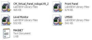
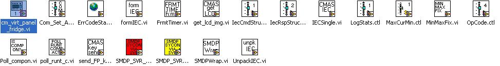
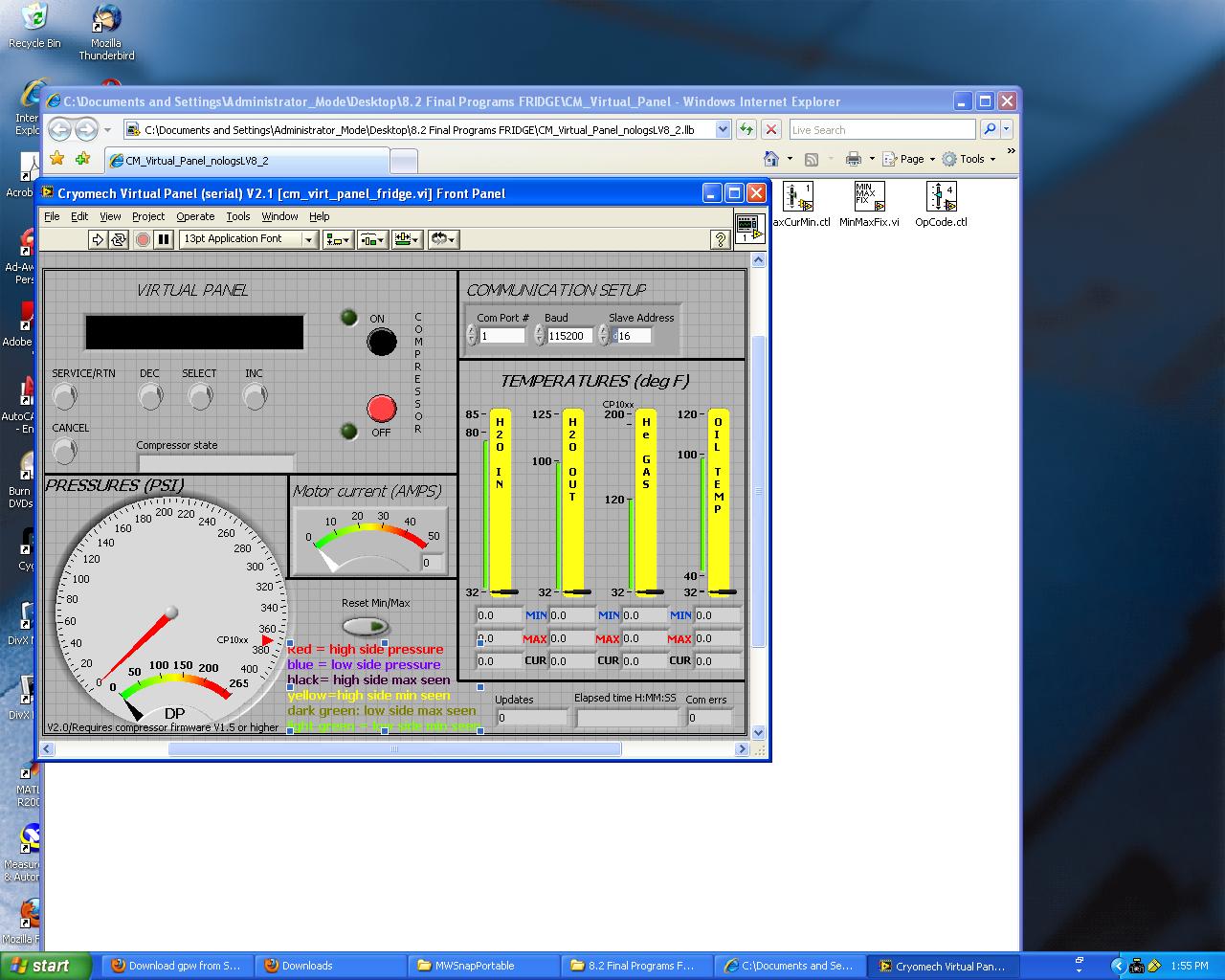
1. There are two seperate folders located on the desktop; one for the magnet software and one for the fridge software. They are identical to set up. We'll set up the fridge (with magnet instructions indicated in brackes) compressor monitoring software for this example. Open the folder called "FRIDGECom08" (MAGNETCom09) 2. There are two files in the folder CM_Virtual_Panel_nologsLV8_2.llb and Front Panel.llb 3. Click on "CM_Virtual_Panel_nologsLV8_2" , this will open a cm_vir_panel_fridge.vi ( if not select it from the library as shown below): 4."cm_vir_panel_fridge(magnet).vi" contains the virtural panel as shown:
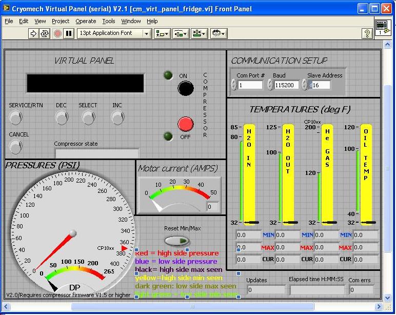 5. in COMMUNICATION SETUP check that com port is set to 8 for the fridge ( and port 13 for the magnet compressor Matt's note - magnet seems to have changed to port 13).
6. Click run (the white arrow on the top left:
5. in COMMUNICATION SETUP check that com port is set to 8 for the fridge ( and port 13 for the magnet compressor Matt's note - magnet seems to have changed to port 13).
6. Click run (the white arrow on the top left:  )
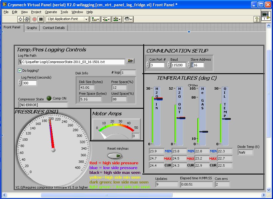
8. When the front pannel is running, it looks as shown below. Now this is runing, it will appear on the QED wiki.
)
8. When the front pannel is running, it looks as shown below. Now this is runing, it will appear on the QED wiki.
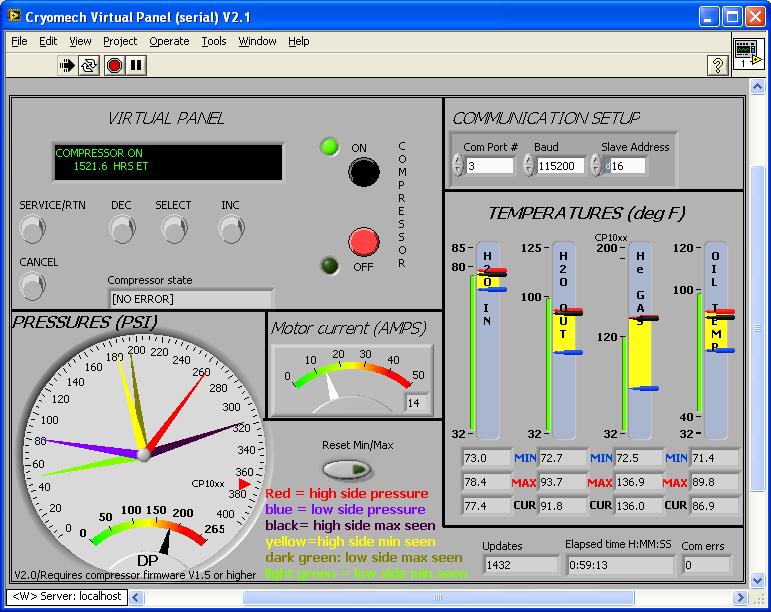 9. Now this is set up, return to the FRIDGECom08 folder and click on Front Panel.llb
10. As in step 3, a cm_virt_panel_fridge.vi should start (if not select it from the library as shown below)
11. The front panel for the comperssor will now open, it looks very similar to that in step 4, however thee are now three tabs on the top left hand side.
9. Now this is set up, return to the FRIDGECom08 folder and click on Front Panel.llb
10. As in step 3, a cm_virt_panel_fridge.vi should start (if not select it from the library as shown below)
11. The front panel for the comperssor will now open, it looks very similar to that in step 4, however thee are now three tabs on the top left hand side.
 12. in COMMUNICATION SETUP check that com port is set to 8 for the fridge ( and port 13 for the magnet compressor - magnet has changed from port 9 to 13).
13. Open the contact details tabe and put in your phone number and email address, and the details of whoever is doing the fridge run. This will contact them if something unexpected happens with the compressors.
14. Click run (the white arrow on the top left: )
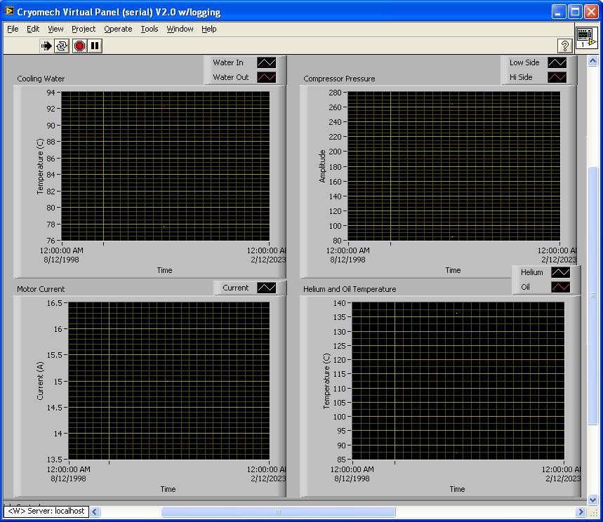
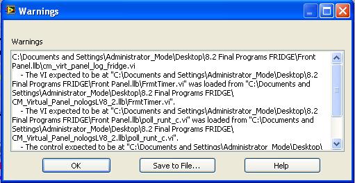
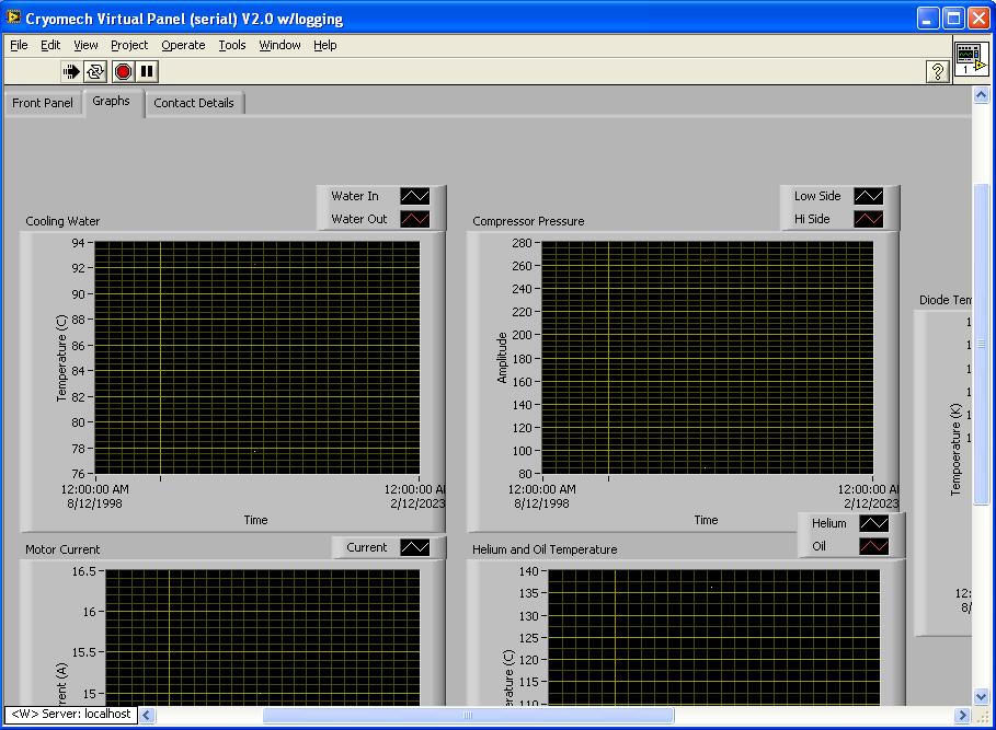
15. Now click on the 'Graphs' tab, and you will see as shown below. Notice you can't see all four graphs, this is what will be displayed on the QED wiki if you don't resize the window.
12. in COMMUNICATION SETUP check that com port is set to 8 for the fridge ( and port 13 for the magnet compressor - magnet has changed from port 9 to 13).
13. Open the contact details tabe and put in your phone number and email address, and the details of whoever is doing the fridge run. This will contact them if something unexpected happens with the compressors.
14. Click run (the white arrow on the top left: )
15. Now click on the 'Graphs' tab, and you will see as shown below. Notice you can't see all four graphs, this is what will be displayed on the QED wiki if you don't resize the window.
 16. Resize the window to appear as followig:
 17. Now repeat for the magnet compressor using folder MAGNETCom09 (com port 9).
18. When done check the wiki to see if all is displayed correctly on VectorFridgeStatus (you will have to refresh the page to see any changes). The page is updated every 15s, you need to refresh your browser to see any changes.
17. Now repeat for the magnet compressor using folder MAGNETCom09 (com port 9).
18. When done check the wiki to see if all is displayed correctly on VectorFridgeStatus (you will have to refresh the page to see any changes). The page is updated every 15s, you need to refresh your browser to see any changes.
Starting the compressors
Now the monitoring software is on, we can run the compressors.- check circulating water is on in the open position
- Start the chiller upstairs
- Start the linear drive for the remote motor (on th mezzanine level - just plug the black box into the mains)
- put the main breaker (botton left) in the up position to supply power to the compressors
- press the green 'ON' button and the compressors (both) will start. A green light above theRS232 connector will flash, indicating the compressor is communicating to the computer.
- record all steps in lab book, as well as pressures/temperatures before and after starting. The compressors will take 53 hours to reach 4K.
Thermalising the fridge to 4K
After running the compressors for 53 hours, the fridge stages will not be at 4K because there is no gas to conduct heat. Therefore exchange gas needs to be heated out of the sorb to release the 4He put in the IVC.- Start 'DR front panel.vi' on the laptop desktop and make it plot data every 1 minute (at the bottom right of the screen)
- under the graphs tab, check ch5,ch6,ch7 and monitor the IVC and still pressure
- Record all temperatures and pressures in the log book before starting.
- Apply 35-40 mV on the SORB heater:
- on TTv2.56.vi (see VectorFieldFridgeThermometryAndHeaterSoftware), select the "TCS Control" tab
- in the I1 (current source one) select the range 1-99mA and enter 35-40 in the 'current' box, press enter.
- the value you want should appear under the "Current Source 1" display box. Notice the current has not yet been applied since the 'ON' button is dim.
- Click the"ON/OFF" button under the TCS control tab to turn the heater on.
- When the fridge is thermalised, turn the SORB heater off (press "ON/OFF" on the "TCS Control" tab).
- Record all actions and fridge parameters in the log book.
Cooling to base
See VectorFieldFridgeCoolingToBase (Let the world see this, co comment out * Set ALLOWTOPICVIEW = QedGroup)Comments


| I | Attachment | Action | Size | Date | Who | Comment |
|---|---|---|---|---|---|---|
| |
10_resize_window_for_graphs.jpg | manage | 140 K | 29 Mar 2011 - 03:09 | SarahMacLeod | |
| |
11.jpg | manage | 116 K | 29 Mar 2011 - 03:47 | SarahMacLeod | |
| |
12.jpg | manage | 99 K | 29 Mar 2011 - 04:00 | SarahMacLeod | |
| |
1_open_folders.jpg | manage | 3 K | 29 Mar 2011 - 03:08 | SarahMacLeod | |
| |
2_open_two_files.jpg | manage | 13 K | 29 Mar 2011 - 03:08 | SarahMacLeod | |
| |
3_open_cm_virt_panel.jpg | manage | 27 K | 29 Mar 2011 - 03:08 | SarahMacLeod | |
| |
4_open_virt_panel.jpg | manage | 187 K | 29 Mar 2011 - 03:08 | SarahMacLeod | |
| |
5_click_run.jpg | manage | 880 bytes | 29 Mar 2011 - 03:08 | SarahMacLeod | |
| |
6_enter_port_three.jpg | manage | 6 K | 29 Mar 2011 - 03:08 | SarahMacLeod | |
| |
7_warning_graphs.jpg | manage | 43 K | 29 Mar 2011 - 03:08 | SarahMacLeod | |
| |
8_open_virt_panel.jpg | manage | 114 K | 29 Mar 2011 - 03:08 | SarahMacLeod | |
| |
9_click_on_graphs.jpg | manage | 120 K | 29 Mar 2011 - 03:08 | SarahMacLeod |
Edit | Attach | Print version | History: r24 < r23 < r22 < r21 | Backlinks | View wiki text | Edit wiki text | More topic actions
Topic revision: r24 - 19 Feb 2024, MatthewRendell


Ideas, requests, problems regarding Foswiki? Send feedback