You are here: Foswiki>QED Web>QedLabStuff>VectorFieldFridge>VectorFieldFridgeMagnetOperation>VectorMagnetOperatingInstructionsDAQVectorMode (09 Sep 2014, RoyLi)Edit Attach
VectorMagnetOperatingInstructionsDAQVectorMode
Swiching the power supplies to Vector mode
to do...Starting the software
BEFORE STARTING THE SOFTWARE: Are ALL of the magnets switched to 'Slave' mode at the back?- Check that the PSU's are in 'remote' mode. (there is a light on the front of the PSUs for each magnet. If they are not lit, press the remote buttons)
- Do not have the magnets in different modes: either they are all in 'USB' mode or all in 'Slave' mode.
- Do not start the DAQ mode software until the 3 power supplies are on.
- The output on the magnet power supply units are meaningless in Vector mode! Read computer output.
- Warning: Vector mode does not have the same safety-features (for the magnet) as does USB mode, so always check ramp-speed, (more detail here)
 3. Menu.vi will appear. Run menu.vi by clicking the white arrow, below 'Edit'. Notice the 'grid' background disappears and becomes a solid green colour. This indicates LabView is running.

menu.vi control window
| Image | What | Comments |
|---|---|---|
 |
Run button | Click this to run the LabView VI |
 |
Start PSU interface | This opens the Vector Magnet Controller which interfaces with the magnet Power Supply Units (PSU) |
 |
Start temperature scanner | This starts the temperature scanner. Always run this first! |
 |
Start sequences window | - |
 |
This is not available on our system. |
 5. Select '2890 Initialisation.ini' file by clicking on the folder icon and selecting the 2890 initialisation.ini file ( check that the path is correct - it MUST be C:\Cryogenic Software\DAQCard-Driven\2890 Initialisation.ini). Click 'CONFIRM'
 6. 'menu.vi' will now appear. Start the temperature scanner by clicking on 'SCANNER'.
 7. The Thermometer Scanner will now start. Press 'Initialise' to start. Press 'New log file' to create a new log file.
Thermometer scanner control window
| Image | What | Comments |
 |
Indicates if scanner is on | The green button is as shown when the scanner is on, and as shown below when off. |
 |
Log file information | The green button flashes when the system is logging temperatures. |
 |
To quit the vi | |
 |
To initialise the scanner | |
 |
||
 |
To display the log file as a graph | |
 |
To create a new log file | The log has to be started manually, start the file name with the date, followed by any other names. |
 9. The Vector Magnet Control.vi window will appear. Upon starting, the software always registers a non-zero magnetic field, therefore ramp to zero first and then set the field you want. Notice:
 - The system is initialised (see text box), meaning you can proceed.
-
The field is non-zero (even if the magnet is at zero field to start with):

-
The system is reporting it is out of range:

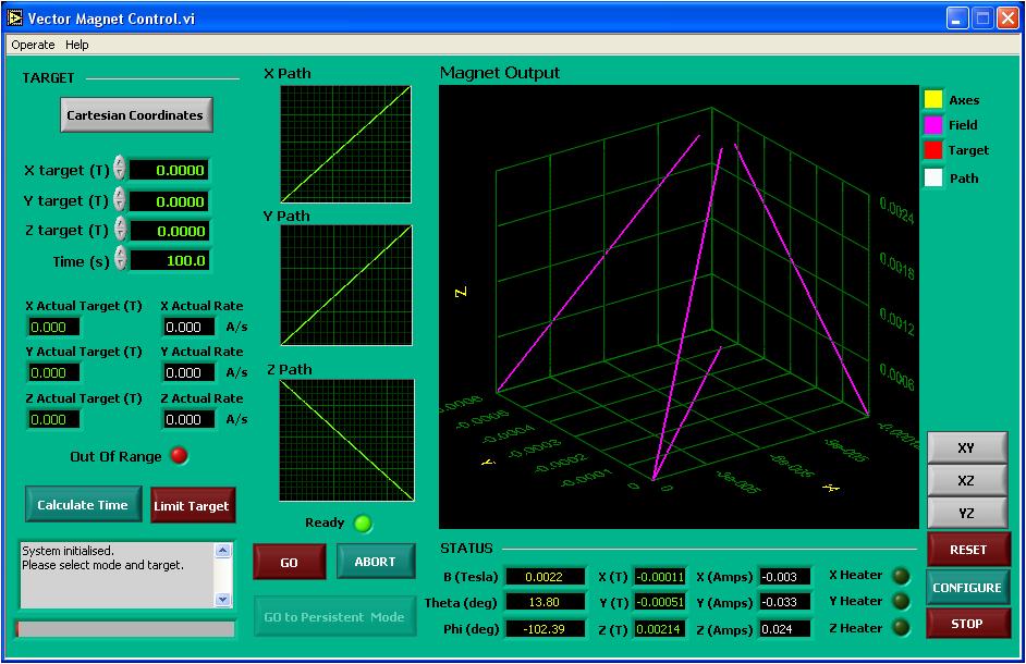
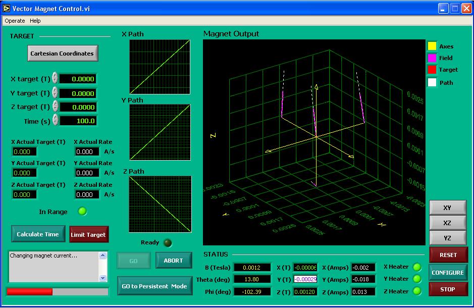
Vector magnet control.vi window
| Image | What | Comments |
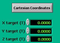 |
Coordinate system and field targets (input) | The grey button indicates which coordinate system is in use, click on it to change coordinate systems. Beneath this is where the desired target field is entered. Either use the 'up and down' click buttons, or simply enter the field in the black boxes. |
 |
Field values and current ramp rate (output) | The ramp rate is not explicitly input, instead it is determined by the input field and the time to reach the desired field (rate=field/time). Therefore always manually calculate the rate in mT/s for each X, Y and Z input value. Be aware if you enter different target values for each magnet, they may have different ramp rates. |
 |
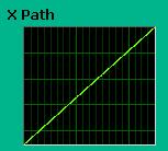
Ramp path (calculated) | These X, Y & Z Path graphs show the ramp path the magnet will take. In the Vector magnet control.vi screen shot above, the magnet will ramp in the positive x-direction, positive y-direction and in the negative z-direction. These graphs are green when the system can ramp at a certain rate, and are red when they cannot ramp at the given input rate. |
 |
Information on setting the field | Here you can see if the field is out of range (too high or too fast): green means the range is fine and red means it is out of range. If values are input into the field target, clicking 'calculate time' usually gives the shortest time to the input value. It is a useful lower range. Limit target..... |
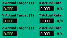 |
Confirmation of field inputs | These display the actual target values in the current coordinate system, in addition to the ramp rates in A/s. This box confims your inputs only. |
 |
Field status (output) | This also reports the field status, in both cartesian and spherical coordinates, as well as the Amps put into the magnets. The green lights, when lit, indicate the heaters are on. |
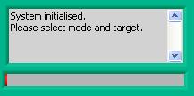 |
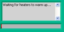
Comment text box and status bar (below) | Above the text box displays the magnet status, for all mangets. Below the status bar indicates the progress during ramping. |
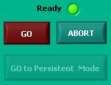 |
Field ramping controls | 'Ready' indicates if the field is ready to be ramped, 'GO' starts ramping and 'ABORT' is to abort mid-ramp. 'GO TO PERSISTENT MODE' is obviously to put the magnet in persistent mode! |
 |
magnet output display (not shown in full here) | Displayed here is the magnet output. When the system is first started only 'field' is shown in purple - this is because the software registers a field upon startup, even if there is not field. |
 |
||
 |
Ramp the field to zero
10. First enter the field value (here it is zero) into all targets/axes. 11. Click 'Calculate Times' so the software registers the input. Notice:
 - The field is now 'In range' and not longer 'Out of range'
- The confirmation of ramp inputs ('Actual...')now displays ramp rates (it did not before).
- The magnet output displays the path (white) and the field (purple)
- The X, Y & Z Path displays are green (okay!)
- The system is 'Ready' (green light is on)
 12. Select the desired time to ramp (for 'real' fields), in the case of initially "ramping" the field to zero so the software registers zero field, you can leave it at 1 second.
 13. The X, Y and Z path displays will change/adjust automatically once you have finished entering the time (or fields). If they are green: start. If they are red input another time.
 14. Click 'GO' to start ramping the field.
 15. The text box on the vector magnet controler will read "Wating for heaters to warm up..." indicating the magnets will start soon.
 16. The vector magnet controller will look as shown below. Notice:
 - The text box displays "changing magnet current" indicating the magnet/s are ramping.
- The progress bar displays the rough progress of the magnet.
- The heater lights are lit up and green, indicating the heaters are on.
- Under 'STATUS' the values are decreasing.
- The 'Magnet Output' also displays the change in magnetic field, shown by the now shorter Field lines (pink).
- The 'GO' button is inactive (as is the 'Ready' button), the 'Go To Persistent Mode' is active as is 'Abort'
 17. When the magnet has finished ramping the text box will display:
 The 'Magnet Output' will display the field (not shown as it's at zero)and path

Ramping the field
18. When ramping the field, do the same as in steps 10-17. The main difference will be in the magnet output display, where 'target' will now be displayed in Red (as shown below), which was not seen previously as we were ramping to zero.
Aborting ramp
1. While ramping, as in Step 16, press the 'ABORT' button. 2. You will see the text box below after aborting the field.

Setting a ramp sequence
(to do)Change the switch heater voltage
It was shown for the 9T Z magnet that increasing the switch heater voltage helps to lower hystereis effects when sweeping the magnet. (note this did not seem to occur with the 5T X magnet). It should be possible to change the switch heater voltage within "Vector Magnet Control.vi" by clicking the 'configure' box and adjusting the settings for each magnet. However, this does not seem to work. Changing the setting and clicking 'save' does not have any effect and the magnet just keeps the original setting (even though the 'configure' panel shows that the setting has changed - it really hasnt changed.) So in order to adjust the switch heater voltage you need to do the following: 0. Make sure that the Cryogenic magnet control "Vector Magnet Control.vi" is not running - stop it. 1.First open "Vector Magnet.llb" following the path "C:\CyrogenicVectorMagnetSoftwareRepo\DAQCard_Driven". 2. Select the "Serial.vi" in the pop-up window.


 3. For the Z-magnet, set the VISA resource name to COM3 in the front panel. The x-magnet is COM7, and y is COM4 (see and y-magnets are on different com ports - see the "2890 Initialisation.ini" file for details.
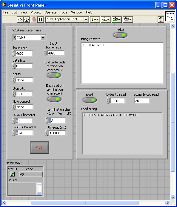 4. make sure the 'read' and 'write' arrows are ON and glowing green. Type in the desired switch heater voltage in the "string to write" section following the syntax "SET HEATER n" and run. For example, "SET HEATER 3.0" will set the switch heater voltage to 3.0V. To check the voltage is set correctly, type in "SET HEATER" and run. The current switch heater voltage will be printed out in the


 "read string" section.
 You can also turn the heaters On and off by typing 'HEATER ON' and 'HEATER OFF' (while you are at zero field)

Access Control
Global read access by default (this line is commented out: Set ALLOWTOPICVIEW = QedGroup)Tags
Comments
Edit | Attach | Print version | History: r10 < r9 < r8 < r7 | Backlinks | View wiki text | Edit wiki text | More topic actions
Topic revision: r10 - 09 Sep 2014, RoyLi
 Copyright © by the contributing authors. All material on this collaboration platform is the property of the contributing authors.
 Ideas, requests, problems regarding Foswiki? Send feedback


